IEDM: GaN powers ahead

Researchers at the recent International Electron Devices Meeting
unveiled record-breaking GaN devices featuring superior architectures.
BY RICHARD STEVENSON, EDITOR, CS MAGAZINE
Within our industry, the standing of GaN continues on its upward trajectory. This wide bandgap semiconductor is entrenched as the ultimate material for making blue, green and white LEDs, and is now strengthening its case for the transmission of RF signals and starting to enjoy a tremendous sales ramp in the power domain. In the later sector, revenue is tipped to soon break the $1 billion barrier, driven by advances in device performance that will ensure energy savings in various consumer and industrial applications.
Underpinning this surge in sales are efforts of researchers in academia and industry – this community is improving established devices and developing new ones. Some of their recent, major breakthroughs were detailed at the 68th IEEE International Electron Devices Meeting (IEDM), held from 3-7 December, 2022, at the Hilton San Francisco Union Square. At that gathering, engineers unveiled new records in power integration, success with high-voltage switches on sapphire substrates, the introduction of a hybrid gate that bolsters threshold-voltage stability, and a debut for the vertical GaN superjunction device.

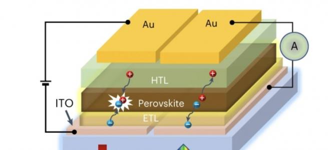
Figure 1.Intel Component Research has progressed its high-κ GaN
transistor (a) to designs with a gate-field plate (b) and a source-field
plate (c).
Optimising field plates
Speaking at the latest IEDM, Intel Components Research Engineer Han Wui Then claimed new records in power integration, accompanied by a new benchmark in the RF. He and his colleagues have been working to improve the performance of GaN devices on a 300 mm silicon (111) platform through the introduction of a pair of scaled field plates.
Intel’s latest success builds on its previous breakthroughs in GaN-on-silicon technology. Back in 2019, the company’s Components Division reported the first industry process for 300 mm GaN-on-silicon, motivated by a desire to better the performance, efficiency and density beyond what is capable with established technologies, such as SOI, CMOS, SiGe, BiCMOS and GaAs/InP HBT/HEMT. The GaN-on-silicon technology they have developed, promising high data rates and the ability to aid 5G communication systems, has already led to claims of best-in-class performance. Previous presentations by Then and his co-workers championed the capability of this technology for voltages of 12 V or below, where it could be used for battery-powered RF front-end modules. That ceiling on the voltage has now been raised, with Then announcing at the latest IEDM that with the introduction of field plates, performance is now far, far better than that of incumbent technologies at up to 40 V.
These field plates are added to a platform that is bringing Moore’s law to GaN, with fabrication of devices with dimensions on the nanoscale involving the use of atomic layer etching, as well as the atomic layer deposition of a dielectric gate. These processes are key to producing two devices: the enhancement-mode high-κ gate dielectric GaN transistor, and the D-mode Schottky GaN HEMT. The two types of transistor can be incorporated into circuits with an interconnect process that features four copper layers and enables tight integration of passives. There is also the opportunity for monolithic integration of GaN and CMOS technologies, using advanced chemical-mechanical polishing and cleaving processes.
For their latest work, Then and colleagues have investigated two different field plate architectures for enhancing device performance at higher drain voltages. One involves a gate field-plated and the other a source field-plate (see Figure 1 for details).
“What we conclude from our research is that the source-connected field plate can achieve the extension of the drain voltage to higher drain voltages, bringing the field plate closer to the 2D electron gas to exert control on the 2D electron gas, and finally scale the source field plate in order to minimise parasitics,” remarked Then.
With the source-field-plate device, which has a 30 nm gate length, a 600 nm gate drain and a 100 nm source field plate, a drain-source breakdown voltage of 70 V is realised, based on a breakdown current of 1 mA/mm. Increasing the gate length of this device boosted breakdown to 92 V. “These are really excellent devices: short channel and high voltages,” claimed Then.
The team from Intel’s Components Division have also considered a figure-of-merit for power: the product of on-resistance and gate charge, which reflects the amount of charge switched in and out of the transistor. Measurement gave values for this figure-of-merit of less than 4 mΩ nC – that’s so low that they are best-on-class for power electronics, according to Then. He added that this value improves with scaling of the channel length.
Additional plots show the true enhancement-mode operation of the devices, with the drain leakage below 0.3 pA/mm at 40 V, for a gate voltage of 0 V; and just 2 V required to turn the MOS gate fully on.
“That really contrasts with what is needed to turn on a discrete GaN pHEMT device,” explained Then. “You will need 5-6 volts in order to turn on those devices.”
Due to this lower voltage, it is possible to integrate a GaN MOSHEMT with a high-κ gate dielectric with CMOS. Even the latter, in the form of a 1.8 V technology, is capable of driving the gate of the GaN transistor.

Figure 2.Intel’s latest GaN devices that incorporate a field plate have a
far better figure of merit, in terms of the product of on-resistance
and gate charge, than all the incumbent technologies.
The engineers from Intel have also investigated the lifetime of their GaN devices. Experiments, showing the benefit of a field-plate, indicate a lifetime for this type of device of 10 years, based on a 10 percent degradation in the on-resistance under a 41 V drain-source stress.
Using a figure of merit that is the product of on-resistance and gate charge, the team benchmarked its device (see Figure 2). “What we see is fantastic figure-of-merit gains over incumbent technologies, such as silicon finFET, silicon LDMOS and pGaN HEMT,” remarked Then. “The figure of merit can be ten times to twenty time higher than all these technologies.”
As well as considering the capability of their devices for power, Then and colleagues have considered RF capabilities. The maximum cut-off frequency (fmax) increases with drain voltage, to hit what is claimed to be a record-breaking 680 GHz at 16 V for the source-field plate transistor. The cut-off frequency, fT, shows a slight decline with voltage, falling to 130 GHz at 16 V (see Figure 3). Benchmarking these results shows that this level of performance far exceeds that for other GaN-on-silicon devices (see Figure 4).

Figure 3. Intel’s field-plated GaN NMOS devices show an increase in fmax and a slight reduction in fT with drain voltage.
Supported by sapphire
For GaN power devices, by far the most common substrate is silicon. However, there’s a very strong case for using sapphire, a platform championed at IEDM by Geetak Gupta, a Senior Member of Technical Staff at Transphorm. In his talk he made a strong case for the merits of using GaN-on-sapphire for the production of 1200 GaN switches.
Transphorm’s motivation for developing this particular product is partly driven by the opportunities in the electric vehicle market, which will increase its production of automobiles running on an 800 V supply over the next few years. The chipmaker could target the deployment of its 1200 V GaN FET on on-board chargers and the driver inverter. Additional markets where this power device might serve include those that require uninterruptable power supplies, the aerospace and defence sectors, server farms and the photovoltaic industry.

Figure 4. Benchmarking Intel’s latest GaN-on-silicon devices reveals a record fmax.
For lower voltages, Transphorm has launched five generations of 650 V transistors on silicon substrates, plus three generations of 900 V variants. According to Gupta, the company is unique in providing the market with a product capable of handling this higher voltage.
To extend the portfolio to 1200 V, it makes much sense to switch the substrate from silicon to sapphire, argued Gupta, as this widely available alternative enables far lower epitaxial costs. “This is because the high voltage is held vertically across the buffer, and as a result, greater than ten microns of epitaxy growth is required to build a 1200-volt device [on silicon].” With sapphire, its insulating nature allows 1200 V GaN FETs to be produced with a very thin buffer layer, trimming epitaxial growth costs and also improving material quality, thanks to less stress in the material.
Processing of GaN-on-sapphire is well established, due to the success of the LED industry. Gupta advocates running 150 mm or 200 mm wafers through a CMOS-compatible fab, followed by further processing using grinding and dicing tools that serve in the GaN LED industry.
Fabrication of Transphorm’s 1200 V devices begins with the growth of a GaN heterostructure that is said to have very good crystal quality, a low dislocation density near the active layers and excellent sheet resistance uniformity. Epiwafers are processed into lateral GaN HEMTs that feature a high-mobility two-dimensional electron gas and a field plate to optimise the electric field profile. Low-voltage silicon MOSFETs with a threshold of around 4 V are attached to these HEMTs to create normally-off switches. To ensure low thermal resistance, the GaN die is directly bonded to the package leadframe with a low void fraction.
Electrical measurements on this switch reveal that off-state leakage is below 2 mA for voltages up to 1200 V, with hard breakdown occurring above 2 kV (see Figure 5). “This gives us an adequate voltage margin for a 1200 volt device,” said Gupta, who added that the switch shows very good output characteristics. Pulsed current in the on-state exceeds 200 A, indicting high-current capability.
Gupta and his co-workers have used a three-dimensional model to evaluate the performance of their switch in a TO-247 leadframe on a copper heatsink. Modelling indicates that thinning the sapphire to 200 µm, a relative conservative value, should ensure a low thermal resistance. Measurements on such a device showed good agreement with the model, giving a thermal resistance of 0.78 °C/W, which is said to be sufficient for high-power applications.
“There is room for further improvement, as substrate thinning to 100 microns is well within the range offered by commercial vendors,” added Gupta.

Figure 5. Transphorm’s GaN-on-silicon switches are capable of handling more than 1200 V.
To evaluate the switching performance of their device, Gupta and colleagues investigated inductive switching in a half-bridge circuit, using 720 V and 28 A. This study revealed a rise time of around 14 ns – the value for SiC is 25 percent higher, even for a much smaller gate resistance; and for the silicon IGBT the value is 140 percent higher. Note that the fall time for the 1200 V GaN switch is just 13 ns.
Thanks to fast rise and fall times, switching loss of the half-bridge circuit operating at 720 V and 24 A is just 510 mJ per cycle. According to Gupta, this value is half that for a state-of-the-art SiC MOSFET.
“We also built a buck converter, to test the efficiency of 1200 volt GaN switches,” added Gupta. Using a pair of 1200 V, 70 mW devices and 50 kHz switching, the efficiency of this converter is above 99 percent. This drops to 98.7 percent at 100 kHz.
“Lastly, we benchmarked our devices against state-of-the-art silicon carbide,” said Gupta, who pointed out that the GaN-on-sapphire variants have a superior figures of merit. “This is reflected in the buck converter efficiency of 1200 V GaN being higher than silicon carbide state-of-the-art MOSFETs.” The extent of this superiority is shown in Figure 6.

Figure 6. In a buck converter, state-of-the-art SiC switches have a loss
that is 8-9 percent higher than GaN-on-silicon variants made by
Transphorm.
Hybrid gates
A decision facing every designer of a GaN HEMT is whether to use a Schottky-type gate for their device, or one based on an ohmic contact. The Schottky-type variant is often preferred, because it offers a lower gate leakage and an enlarged operation voltage swing.
However, the Schottky-type gate does have its weaknesses. In a presentation delivered by Chi Zhang from Southeast University, China, he explained that a drawback of the Schottky-type gate is that it can lead to charge storage, stemming from the use of back-to-back diodes.
The reason for this, according to Zhang, is that the depletion region in the Schottky-type gate can result in a “floating p-GaN layer”, sandwiched between the gate and the channel. It is difficult to remove charges in this layer, induced by a drain bias, and these carriers lead to a shift in the threshold voltage – in a commercial Schottky-type GaN HEMT, this shift is typically as high as 0.42 V. This increase in threshold voltage is undesirable, leading to a higher on-state resistance and reduced system efficiency.
While an ohmic gate can combat these issues, it also results in a large gate leakage. What’s more, there’s a need for a higher continuous gate current to maintain an on-state operation voltage.
A far better option, argues Zhang – who has been working with colleagues at Southeast University and at Nanjing Electronic Devices Institute – is to introduce a new, hybrid gate architecture that ensures a low gate leakage current and a small threshold voltage shift.
To fabricate the transistors, the team began by loading a 2-inch silicon substrate into an MOCVD chamber and depositing a 5 µm-thick buffer layer, followed by a 300 nm-thick undoped GaN channel, a 15 nm-thick Al0.23GaN0.77N barrier and a 70 nm-thick p-GaN layer with a magnesium doping concentration of around 2 x 1019 cm-3.

Figure 7. A team led by researchers from Southeast University, China,
are pioneering GaN HEMTs with a hybrid gate. The fabrication of these
transistors involves the deposition of a Ti/Au (20 nm/80 nm) metal
stack, followed by the formation of a Schottky contact on the p-GaN
layer and top ohmic contact regions by the addition of 100 nm of
tungsten.
These engineers formed the hybrid gate (see Figure 7) by using an e-beam evaporator to deposit 20 nm of titanium, followed by 80 nm of gold. Lift-off followed, before forming the Schottky contact on the p-GaN layer and the top ohmic regions by depositing 100 nm of tungsten and then undertaking patterned lift-off. Using the Schottky gate metal as the hard mask, they etched a p-GaN region with a self-aligned process. Source and drain contacts were created by depositing a metal stack with an e-beam evaporator, prior to thermal annealing under nitrogen gas for 45 s at 840 °C.
Transmission line measurements on the hybrid-gate HEMT revealed a contact resistance of 101 Ω mm and a resistivity of 0.003 Ω cm2.
“In order to verify the reliability of the hybrid gate HEMT, Schottky HEMTs fabricated by the same production line on the same wafer were also investigated as a comparison,” remarked Zhang. “The results indicate that the hybrid-gate structure has no impact on the concentration of the p-GaN layer. The hybrid-gate structure only adjusts the Schottky diode formed by the gate metal and the p-GaN layer. The p-i-n diode – consisting of the p-GaN layer, barrier layer, and channel layer – is not affected, due to the same process steps.”
Zhang and co-workers have also considered the change in the performance of their devices at elevated temperatures. Increasing the temperature from 300 K to 400 K shifted the threshold voltage by less than 0.3 V.
Measurements on a conventional Schottky diode HEMT showed a long-term shift in the threshold voltage of around 0.2 V (see Figure 8). During DC gate bias stress, the emitted holes accumulated in the p-GaN layer, and after removal of the bias, holes could not exit this region, causing the threshold voltage to decrease. “Significant advantages can be observed in hybrid-gate HEMTs, where almost no threshold voltage shifts happen after 1200 seconds DC gate bias stress,” added Zhang.
The hybrid gate structure also ensures a superior performance under drain bias. For the conventional Schottky diode HEMT, the threshold voltage shifted by 0.7 V, compared with a shift of less than 0.03 V for the hybrid device.
To evaluate reliability, Zhang and colleagues measured the breakdown voltage of HEMTs with a Schottky gate, an ohmic gate and a hybrid gate. All three variants exhibited a very similar breakdown of around 10.6 V, indicating that the breakdown mechanism is independent of the junction between the metal and p-GaN. Using a drain-source voltage of 9 V, current-transient measurements unveiled energies for the traps of 0.69 eV and 0.59 eV, for the HEMTs with the Schottky gate and the hybrid gate, respectively. “This information indicates that hybrid-gate HEMTs own shallower traps, leading to easier discharge of the induced stored charges,” concluded Zhang.
The team have also investigated the performance of their novel HEMTs in a circuit producing unclamped inductive switching. Subjecting the equivalent circuit with a Schottky gate HEMTs to 2 million unclamped inductive switching cycles produced a shift in the threshold voltage. This shift is not observed in the circuit with the hybrid-gate HEMT, underlining the promise of this device.
A related study considered the repetitive reverse freewheeling stress, with measurements of gate capacitance. “After 1000 cycles stress, the measured gate capacitance indicates that no gate charge storage mechanism occurs in the p-GaN layer for hybrid gate HEMTs,” remarked Zhang, adding that this helped to ensure gate reliability.

Figure 8. Stress tests reveal the superiority of the hybrid HEMT, in terms of a reduced voltage shift.
A debut for the superjunction
Another highlight in the development of GaN power devices at IEDM came from the unveiling of the first vertical superjunction device in this material. Yuhao Zhang from Virginia Tech made that claim, describing work accomplished through a collaboration between his group and researchers at the University of Southern California, Enkris Semiconductor, the University of Cambridge, Qorvo and the US Naval Research Laboratory.
The attraction of any superjunction is that it can overcome the trade-off between the blocking voltage and the on-resistance that limits the performance of one-dimensional devices. Silicon super-junction devices are already well-established, netting billion-dollar revenues per annum, while those made from SiC were first unveiled in 2016. Now GaN has joined the ranks, delivering impressive results.
“To make the superjunction in GaN is very challenging,” remarked Zhang. He explained that one of the two standard approaches, the creation of trenches that are subsequently filled, is susceptible to interfacial impurities and high leakage currents. Meanwhile, the alternative, involving multiple epitaxial steps and ion implantation, requires high-pressures and temperatures for activation – and re-growth can result in re-passivation.
Zhang and co-workers have pursued a novel trench-filling approach that avoids the issues associated with standard methods. Their solution is to fill the trenches with a layer of NiO – it has previously been shown to provide a conformal coating on GaN, handle high electric fields and offer good thermal stability. NiO has a bandgap of around 3.4-4.0 eV, a critical electric field of up to 5 MV/cm, and a dielectric constant of 11.9, which is higher than that for GaN.
Before fabricating devices, the team modelled the performance of the superjunction. Efforts began by considering the dimensions of the GaN pillars, with calculations revealing that they should be around 2-3 µm wide, and have a donor density of the order of 1017 cm-3. After this, they thought about the NiO filling.
“We wanted to explore the possibility of not having the trench fully filled by the p-type material,” said Zhang. “In this way we can use the p-type material with a much higher acceptor concentration. This may essentially make the sputtering process easier.”
Modelling supported this approach, with the electric field distribution having a similar profile for trenches that are completed filled with NiO, and those that are just partially filled.

Figure 9. A collaboration led by Yuhao Zhang and co-workers at Virginia
Tech has produced the first GaN device featuring a superjunction.
Armed with this insight, the researchers investigated the growth conditions for sputtering NiO with an appropriate doping concentration. They considered three recipes: just argon, a mix of argon to oxygen in the ratio 20 to 1, and a mix of argon to oxygen in the ratio 2 to 1. The later produced a very high hole concentration, exceeding 1 x 1019 cm-3, according to Hall measurements. More suitable concentrations resulted from other recipes, with just argon resulting in a value of 5-6 x 1016 cm-3 and the mix of argon to oxygen in the ratio of 20 to 1 producing a value of 4-5 x 1017 cm-3 – both approaches were used in device fabrication, with prior modelling employed to optimise dimensions.
Fabrication of the devices began by loading a 2-inch GaN substrate in an MOCVD reactor and depositing: a 0.8 µm-thick layer of GaN, doped with silicon at a concentration of 2 x 1018 cm-3; an 8 µm-thick layer of GaN, doped with silicon at a concentration of 9 x 1016 cm-3; a 300 nm-thick layer of GaN, doped with magnesium at a concentration of 1 x 1019 cm-3; and finally a 40 nm-thick layer of GaN, doped with magnesium at a concentration of 1 x 1020 cm-3. To provide a comparison, the team deposited an identical structure on sapphire, apart from the initial growth of heavily doped n-type GaN layer around 4 m-thick, designed to trim current crowding in the quasi-vertical device.
Processing the epiwafers into devices began by adding a p-GaN ohmic contact, in the form of Ni/Au stripes, and then a thick layer of nickel (see Figure 9, which also details the processing steps). The addition of a mask followed, before etching created a mesa. Removal of this mask followed, prior to deposition of SiO2 that surrounds the mesa. Pillars were then etched, and the sidewalls treated with tetramethylammonium hydroxide to improve surface quality. To compete device fabrication, the researchers added the anode and cathode, and filled the trenches with NiO.

Figure 10. Many steps are required to produce the GaN superjunction diode.
Focussed-ion beam, scanning electron microscopy images of the trench region showed that the growth in just argon led to coalescence of NiO at the top of the trenches (see Figure 11). This does not take place in the other device, which is the only type that the team characterised with electrical measurements.
These investigations revealed a breakdown voltage of more than 1100 V for the superjunction diodes formed on both silicon and sapphire.

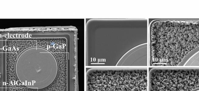
Figure 11. Focussed-ion beam, scanning electron microscopy images (a),
(b) and (c) of the trench of a GaN superjunction diode show that growth
in just argon leads to coalescence of NiO at the top of the trenches.
Growth with an argon-to oxygen ration of 20 to 1 avoided coalescence.
Benchmarking devices against other vertical GaN diodes, considering the blocking voltage and differential on-resistance, indicated that the team’s device is amongst the best for GaN-on-GaN diodes. “If we look at the effective drift region thickness with breakdown voltage, you see that the gallium nitride super-junction compared with the one-dimensional devices allows for the more efficient utilisation of the epi-thickness to boost the breakdown voltage,” commented Zhang (see Figure 12).
Figure 12. The vertical super-junction device delivers a superior performance to one-dimensional equivalents.
Zhang also compared the performance of his team’s superjunction device with those made from silicon and SiC, pointing out that despite the wider pillar width, the GaN device has a much lower specific on-resistance. “This suggests a good potential for out-performing the silicon carbide superjunction with a further scaling of the pillar width.”
Efforts such as this, and the other breakthroughs reported in GaN at IEDM, suggest that the performance of commercial GaN devices will continue to improve. This should help to drive up sales of GaN power devices and increase the reach of this material system throughout our world.