

Revolutionising circuit protection

Custom-based modules made from SiC MOSFETs minimise the impact of short circuits and overloads
BY DENIS KOUROUSSIS FROM ATOM POWER
At some point in the career of nearly every electrical engineer they would have wondered whether it is possible to design a circuit breaker that is not mechanical in nature. Many will reason: Isn’t it better to use a semiconductor to break a fault or handle an overload?
However, when they delve more deeply into this issue, they’ll start to run into roadblocks. One is that the power devices that they are familiar with have a breakdown voltage of around 600 V, so many of them would have to be stacked in series, even when making a circuit breaker for a low-voltage industrial applications that runs off a 480 Vrms AC supply.
Another issue is that when the power flows through any semiconductor device, it creates substantial heat, due to resistances that are significantly higher than those of traditional metal contacts. As this heat must be dissipated, the entire architecture of today’s circuit breaker has to be ‘re-thinked’, before starting to design this product.
Given all these challenges, why would you want to make a solid-state circuit breaker? After all, aren’t the existing mechanical ones, which have been around for over a century, up to the task?

Figure 1
Combatting arc flash
Unfortunately, mechanical breakers are far from ideal in the electrical circuit protection space where by far the biggest problem is arc flash. That’s the name for the amount of energy let through during a short-circuit condition. When mechanical circuit breakers attempt to shut off the current, there is a delay associated with opening this device of typically 8 ms or more. Although a mechanical response of 8 ms is extremely fast for a mechanical contraption – it is probably the physical limit for a metal contact disconnection – in electrical terms it is a ‘lifetime’. During those precious milliseconds a short-circuit fault current can develop from a power source that provides as much as 10 kA or 100 kA, depending on the size rating of the upstream transformer. In this situation, energy dissipates at the fault, with a value that is proportional to the square of the current, which varies with time. At this fault, the flow of energy is often so rapid that it creates an arc blast of molten metal. It is only after this, when the fault current reaches levels of 10 kA or 100 kA, that the circuit breaker will dissipate a significant arc internally upon opening, in order to extinguish the particular massive fault current.
Some good news is that there are benefits associated with the power that comes from the national grid, due to it being in AC form, rather than DC. This means that at least the fault current crosses zero at some point during the half cycle, helping to extinguish the arc within the circuit breaker.
During the past two decades, there have been more initiatives focusing on educating engineers about arc flash. However, efforts have not tackled the origin of the problem head-on, because it is not possible to increase the mechanical speed of opening contacts. Instead, programmes have aimed at minimising the damage that arc flash can cause. This has led to reinforcing both switchgear and the casings of protective devices, as well as training technicians, so that they understand what the appropriate personal protection equipment is for operating circuit breakers and for working near live equipment. In addition, the electrical industry has started to adopt current-limiting breakers and current-limiting fuses that trim the short-circuit current.
But none of these approaches are ideal. The real solution is to open faults within microseconds or less, so arc flash is never a problem. As solid-state circuit breakers make that possible for the first time, they promise to revolutionise electrical infrastructure.
The challenge of selective co-ordination
When engineers try to ensure electrical protection, they need to consider the issue of selective co-ordination. In every electrical distribution system, any fault in the system must be cleared by the closest circuit breaker upstream. This must be accomplished without bringing down the entire electrical distribution system. As mechanical circuit breakers have large varying tolerances for their time curve characteristics, the upstream circuit breaker must have a longer time delay for its time curve characteristics than any downstream breaker.
To illustrate this point, and consider its ramifications, imagine an industrial application with a 2000 A circuit breaker straight from the utility mains. This is feeding a downstream breaker of 150 A that supplies a chiller system. The
150 A breaker for the chiller may have an opening time between 8 ms at best and 13 ms at worst. By knowing this spread, defined in the time curve characteristics provided by the manufacturer, an engineer can apply best practice. To ensure that the entire facility does not drop power if there is a short circuit in the chiller, the engineer requires the upstream 2000 A breaker to have a best opening time of longer than 13 ms. Due to the wide time band that the 2000 A breaker will have, it needs to have an average opening time of 20 ms or more, compounding the challenge of arc flash.
In stark contrast, solid-state circuit breakers are not impaired by the mechanical limitations in clearing time. Thanks to this, they offer a faster response at the point of fault, reducing the time required for a co-ordinated response from the overall circuit protection system.
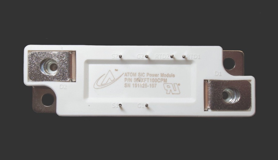
Figure 2
The SiC solution
Efforts to develop solid-state circuit breakers have been aided by developments in other industries. During the last ten years, electric vehicles have started gaining traction, creating demand for more efficient converters operating at higher voltages. Success is highly prized, as it increases vehicle efficiencies and enables that most coveted of assets – a longer driving range. Key to realising this are more efficient devices with lower on-resistances and minimal losses. If these devices are operated at higher voltages there is less current for the same power, enabling a reduction in the use of copper and other conducting materials, and ultimately reductions in weight and cost.
Several companies have invested heavily in developing SiC devices. Efforts have led to MOSFETs, IGBTs and JFETs that can block up to 1700 V, while offering a far lower on-resistance than their traditional silicon counterparts. SiC power devices also switch far faster, enabling inverters to be smaller, have lower switching losses, and potentially retail for less. Thanks to all these advances, SiC devices are the prime candidates for low-voltage circuit protection.
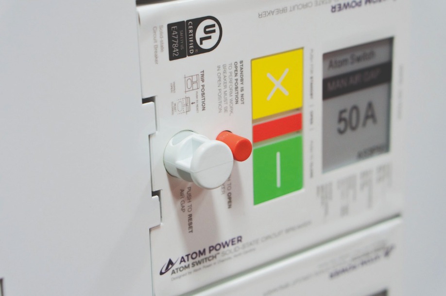
Figure 3
It is already possible to go out and buy a variety of 900 V to 1200 V SiC MOSFETs that have far lower on-resistances than silicon die with equivalent areas (see, for example, Figure 1, showing a 900 V MOSFET with 100 A capability). By turning to these higher blocking voltages, SiC devices can be deployed in the low-voltage circuit protection space, serving 1000 V and less.Note that the majority of applications for these off-the-shelf devices are in the inverter markets, providing DC to DC, AC to DC, and DC to AC conversion. For these tasks, components are housed in discreet packaging, making them unsuitable for use in solid-state circuit protection. If off-the-shelf components were used to produce solid-state circuit breakers, the likelihood is that they would be too bulky. An additional complication is that when MOSFETs are deployed, they need to be in a common-source tied configuration to ensure that AC voltages can be blocked bi-directionally. Due to all these issues, solid-state circuit breakers require a custom module.
When designing a solid-state circuit breaker, it is critical to consider the on-resistance of the transistors. For a SiC MOSFET, this is in the range of 10-20 mΩ. That’s significantly better than comparable silicon devices, which may have an on-resistance 60 mΩ or more – and also a lower blocking voltage. However, even though the SiC MOSFET provides far better performance than its silicon counterparts, its on-resistance is still not trivial, due to the potentially large currents that it needs to pass. For example, if a SiC MOSFET with a 10 mΩ on-resistance has to pass 100 A, then the power it dissipates – the product of resistance and the square of the current – is 100 W. As that’s for just one device, and a circuit breaker will require two in series, dissipation will total 200 W. Such a high power will require a heat sink, and will reduce the efficiency of power delivery through the circuit breaker.
One of the virtues of using SiC MOSFETs is that when they are arranged in parallel, they share current very well, thanks to resistances that are proportional to temperature. Consider two of these transistors in parallel: as current passes through one of them, it heats up the die and resistance rises, effectively pushing current through the second die until the temperatures and resistances balance.
When SiC MOSFETs are placed near to one another on the same substrate, their temperatures are closely linked. Using this approach, one can produce a symmetrical layout that ensures not only current sharing, but equivalent values for stray inductances, capacitances and inherent resistances of metal conductors. With such an architecture, designers can ‘parallelize’ as many devices as they wish, theoretically lowering the on-resistance to any level. In this case, the limiting factors for the size of the SiC area used to trim the on-resistance are the financial implications, and the form factor for the solid-state circuit breaker.
Module design
When an engineer designs a module for solid-state circuit protection, their considerations are markedly different from designing one for an inverter. The latter incorporates high-speed switching, and will have minimal inductances and capacitances to ensure low losses. In contrast, with a circuit protection device, there is no need to consider switching in any form. That’s because this device will be conducting for the majority of its life, and there will only be a handful of turn on or off events.
What is important when designing a circuit protection module is to keep inductances and capacitances equivalent amongst parallel devices. This is critical when an overload or short circuit occurs, as currents can be significantly elevated within the module, and a balanced current needs to pass through all the parallel devices as the gate voltage is reduced (assuming an n-type device) to bring that elevated current to zero. Another requirement is that all the gate connections to the parallel devices have equivalent impedances, to ensure a uniform current turn-off profile amongst the devices. By fulfilling all of these principles, all devices will undergo the same level of electrical stress during a turn-off event, maximising the endurance and the reliability of the module.
Steps should also be taken to minimise the overall on-resistance of the packaged module. This includes considering metallization traces on the substrate and wire bonds, and maximising the cooling for each of the SiC power die, as this reduces the internal module and die temperatures.
At Atom Power, a start-up founded in 2014 and located in Charlotte, NC, we have followed all of these guidelines when designing our 900 V, 250 A power module (see Figure 2). It has a total on-resistance of 7 mΩ, and turn-on and turn-off times of 0.1 μs. Our module forms the basis of a solid-state circuit breaker that we have dubbed the Atom Switch (see Figure 3). It is the first of its kind to gain approval from the Underwriters Laboratory, an independent institution with responsibility for safety standards. Our Atom Switch is a UL489 listed product that virtually eliminates the risk of arc flash and effectively reduces tripping time, thanks to the correct packaging, including current sense, intelligence and control in the circuit breaker. We have tested our product under 100 kA, 150 kA and even 200 kA short-circuit conditions. In all cases it satisfies every requirement without any hardware modifications.
We have designed our Atom Switch to work within the Atom Panel. This provides proper mounting, as well as communications and sufficient thermal transfer to ensure that modules keep cool (see Figure 4).
With our Atom Switch, there is a typical delay of 40 μs for opening under a short-circuit condition. That is far longer than the time taken for the module to switch – that is around 0.1 μs – with the difference coming from a combination of the delay of fault-current rise time of the short circuit, and detection and signalling to turn off the module on the event. However, 40 μs is still incredibly rapid, given that it’s 200 times shorter than the fastest mechanical circuit breakers on the market today. By opening so fast, the energy that is let through falls by a factor of 4000.
An additional benefit of our SiC-based circuit breaker is that unlike a mechanical breaker, it does not need replacing after it has interrupted full-rated short-circuit currents a few times. Yet another merit is that for low overload conditions that are one-to-two times the current rating, the tripping characteristics can be set extremely precisely, with a less than a 1 percent accuracy for tripping time. In comparison, for mechanical circuit breakers, the allowance is up to 10 percent.
Our next generation of Atom Switch will incorporate a ground-fault circuit interrupting capability and an arc-fault circuit interrupting capability. These innovations, realised by employing significantly more algorithmic implementations, will address a significant proportion of nuisance tripping, which is an issue in mechanical circuit breakers – in particular, they struggle to cope with arc-fault circuit interrupting.
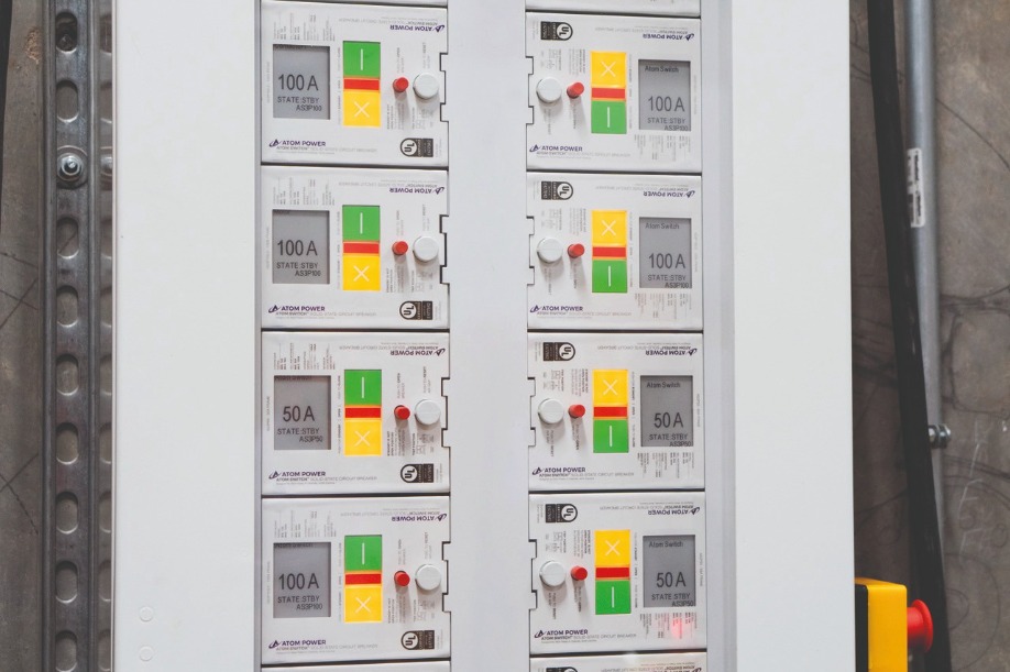
Figure 4
Beyond circuit protectionMaking an even more compelling case for our solid-state circuit breakers are the numerous additional advantages of this technology. One of its benefits is the opportunity to adjust the time curve characteristics through software, so a product can be used for multiple applications, or re-used when the equipment is placed in a different environment.
Additional attributes include self-maintenance and diagnostics. As the solid-state circuit breaker can incorporate intelligence, it can: effectively self-diagnose its own functionality, and ensure correct operation; and generate an alert when a problem has developed, thereby preventing a catastrophe. With mechanical breakers, that’s not possible, as problems are only detected after a fault has occurred, which often ends in a catastrophic event that causes significant damage. Another feature of the solid-state circuit breaker is its remote controllability, making it a great candidate for both demand-management applications and for microgrid islanding, where back-up and alternative power sources may be used. And yet another feature of the solid-state circuit breaker is providing a soft-starter for induction motors and transformers, by emulating a silicon-controlled rectifier.
Today, our solid-state circuit breakers command a higher price tag than their ‘equivalent’ mechanical counterparts. But they are vastly superior on many fronts, offering safety and features that far surpass the capabilities of traditional circuit protection equipment. Due to these merits, their use can eliminate additional equipment deployments, or meet critical safety concerns, making them an attractive purchase.
There is good reason to believe that the cost of these solid-state units will fall, due to a ramp in SiC device production to cater for electric vehicle production, smart-grids and solid-state circuit protection. While mechanical breakers will not disappear overnight, it’s clear that their days are numbered.


