Technical Insight
Adding colour to future silicon ICs
BY BING WANG, LI ZHANG, KENNETH ENG KIAN LEE, FAYYAZ MOIZ SINGAPOREWALA, EUGENE A. FITZGERALD AND JURGEN MICHEL FROM SINGAPORE-MIT ALLIANCE FOR RESEARCH AND TECHNOLOGY
GaN-based LED lighting is now commonplace. High-brightness, white-light emitting chips that hit the market about two decades ago are in our light bulbs, and they are backlighting our smart phones, tablets and TVs.
Unlike many compound semiconductor devices, the GaN LED is grown on a variety of substrates. Due to the lack of an affordable native platform, makers of these emitters are predominantly producing them on sapphire, although several firms are undertaking high-volume manufacture on SiC or silicon. Although heteroepitaxy on all these substrates leads to the formation of many dislocations, fortunately these imperfections do not prevent the manufacture of LEDs with very impressive levels of efficiency.
There are several compelling reasons for selecting silicon as the foundation for GaN LED production. Manufacturing on this material enables the use of a more common substrate, which has been employed in the microelectronics industry for over half a century. This substrate is also cheaper than any of the alternatives, it is available in larger sizes, and it is compatible with well-established CMOS wafer and chip processing and packaging technology. Together these benefits lead to substantial cost savings, with a switch in production from GaN-on-sapphire to 200 mm GaN-on-silicon epiwafers generating cost savings of 60 percent, according to estimates by Samsung. What's more, with this particular material technology, it is possible to address markets beyond general lighting, by integrating GaN LEDs with silicon CMOS circuits.
Figure 1 (a): A low threading dislocation density can be realised with compositional-graded GexSi1-x buffers. However, the total thickness of the layers is typically 10 µm. (b) Using low temperature nucleation and high temperature growth, the germanium grown on silicon can achieve a low threading dislocation density of around 107 cm-2, but with a total thickness that can be as low as about 1 µm. By using arsenic doping in the nucleation stage, the low threading dislocation density can be further decreased by a factor of 5.
Given this wonderful set of attributes, it is not surprising that many manufacturers of LEDs are evaluating devices made on silicon. Although performance was initially inferior to the GaN-on-sapphire LED, thanks to advances in epitaxy, this difference is now very small.
The growth of GaN-on-silicon creates LEDs that can span the green and blue regions of the visible spectrum. For a white light source, emission in the red is also required, which can be realised by adding phosphors to these chips. But this leads to losses associated with down-conversion, so for next-generation, ultra-efficient solid-state lighting, green and blue emitters must be combined with red LEDs.
Realising red LEDs
Red LEDs are typically made with AlGaInP, a semiconductor with a smaller bandgap than GaN and a higher electrical-to-optical conversion efficiency. These devices are grown on GaAs substrates, which are smaller, far more fragile and more expensive than silicon. So a switch to a silicon substrate would be beneficial. Implementing this, however, is very challenging for several reasons.
One of the biggest issues is that the AlGaInP used for making red and yellow LEDs has a 4 percent lattice-mismatch with silicon. This mismatch across a single interface leads to the generation of many threading dislocations, which are detrimental to the performance of the AlGaInP LED. Another downside is that the interface between AlGaInP and silicon is heterovalent, so films of the quaternary are riddled with other forms of defects, such as anti-phase domains and stacking faults. Due to these issues, progress with AlGaInP LEDs on silicon substrates has been slow, with performance lagging that of their GaN-on-silicon cousins.
To address the high density of dislocations that result from direct epitaxy of GaAs and/or AlGaInP on silicon, it is possible to employ a high-quality buffer layer with an intermediate lattice constant to bridge the lattice mismatch. Germanium is a great choice, thanks to a lattice-mismatch with GaAs that is significantly smaller than that between silicon and GaAs.
Figure 2: (a) Due to the thermal expansion mismatch between III-V layers and silicon, the wafer has a concave bow after epitaxy. (b) It is possible to decrease wafer bow by applying compressive strain in III-V layers.
A high-quality heterostructure results from the cyclical annealing of germanium. This yields the lowest possible threading dislocation density for a single mismatched interface in this lattice constant range. Dislocations can be driven even lower by gradually adding germanium into silicon to create a compositional-graded GexSi1-x buffer with a thickness of approximately 10 µm. Such a structure has already provided the foundation for AlGaInP micro-LED arrays.
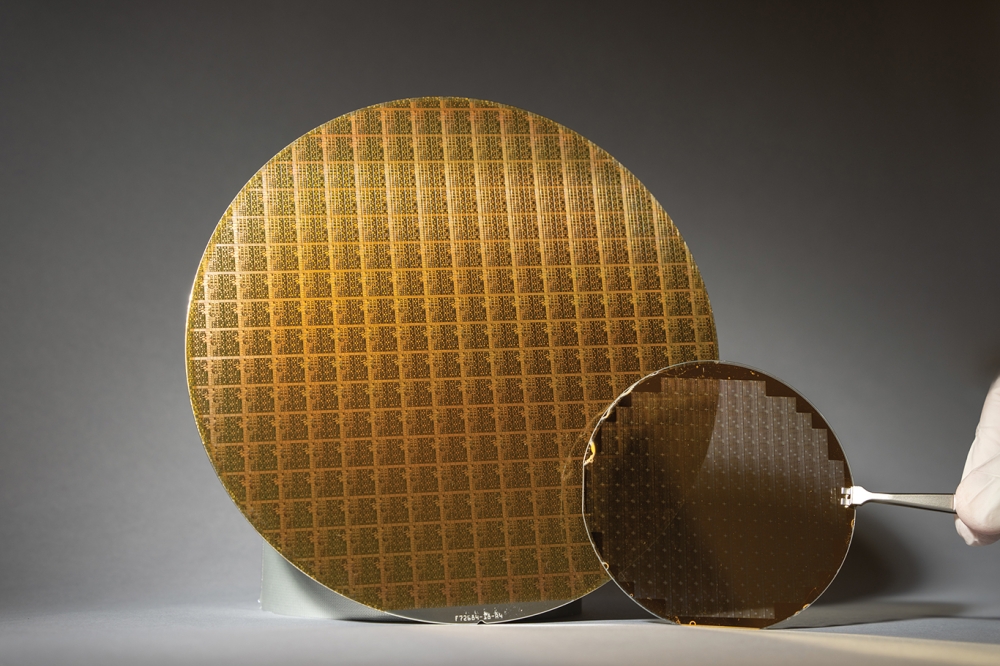
Figure 3: Nomarski microscopy image of an AlGaInP LED 200 mm wafer. The wafer bow is about 45 µm.
Thinning the buffer
At the Singapore-MIT Alliance for Research and Technology (SMART) Low Energy Electronic Systems (LEES), we are following in the footsteps of the pioneers of red LEDs on silicon by developing a high-quality germanium buffer with a two-step growth method. Our approach involves depositing a thin germanium nucleation layer at low temperature, followed by regular high temperature growth.
Although this approach is not new, care must still be taken to ensure uniform high-quality films on the 200 µm silicon substrates. By optimizing growth parameters, the threading dislocation density can plummet to the mid-107/cm2 range after the growth of just 1 mm of germanium. This creates a high-quality germanium buffer, which can serve as an excellent template for subsequent III-V epitaxy. (Note that it is possible to realise a further five-fold reduction in the dislocation density by introducing high arsenic doping in the nucleation stage. However, this technology for reducing defect density has not been used in the LEDs described in this feature.)
The next challenge is the growth of the heterovalent interface. If anti-phase domains and stacking faults are present at the heterointerface, GaAs-on-germanium films will be riddled with threading dislocations. These dislocations, and the anti-phase domains and stacking faults, act as non-radiative recombination centres, slashing the efficiency of LEDs grown on this heterostructure. What's more, the anti-phase domains propagate to the film's surface, resulting in rough surfaces.
The anti-phase domains arise from the exact (001) silicon and germanium surfaces, which have a plethora of mono-atomic steps. So, to avoid them, we use (001) wafers that are 6Ëš offcut to the nearest <111> direction. This approach ensures the formation of double atomic-stepped surfaces.
To realise high-quality epitaxy, we found that in addition to using a high-temperature, pre-growth bake of the germanium buffer to fully activate double-atomic stepped surfaces, it is critical to optimise the arsine partial pressure. Do this, and defects are suppressed during GaAs nucleation, so this layer has a threading dislocation density that is as low as that in the germanium layer.
Another downside of the growth of III-V-on-silicon device layers is the mismatch of coefficients of thermal expansion. This difference induces stress in the epitaxial layers and causes wafer bow, which can be particularly severe when large silicon wafers are used.
For AlGaInP LEDs grown on 200 mm silicon, bowing can exceed 100 µm. This level of bow hinders many critical wafer-scale processes, such as wafer bonding and lithography. Complicating matters, strain in the AlGaInP leads to a rough surface "“ and it also produces changes to the bandstructure, which push emission from the active region to longer wavelengths.
Figure 4 (a) Current-voltage characteristics and electroluminescence spectra under different injection currents of a 1 µm à— 1 µm LED.
(b) Photoluminescence peak wavelength mapping across a 200 mm LED wafer.
To overcome all these problems, we incorporate compressive strain in our AlGaInP layers. This compensates for the tensile strain from thermal expansion mismatch. Taking this approach creates wafers that are flatter and have a better surface morphology. Typically, our wafers have a concave wafer bowing below 50 µm, which is acceptable for most 200 mm wafer bonding, processing and lithography steps.
Using this approach, we have produced, we believe for the first time, red LEDs with AlGaInP multiple-quantum-wells on 200 mm silicon substrates. Photoluminescence mapping reveals excellent uniformity, with a wavelength variation across the whole wafer of less than 2 nm. We have also demonstrated the operation of these red LEDs. While we have not made fully quantitative power measurements, we estimate our devices to emit in the microwatt range and above based on simple photodiode measurements.
As well as optimizing epitaxy, we have explored wafer-scale processing and CMOS-integration. This has enabled our group to create novel engineered substrates by transferring layers from front-end silicon CMOS wafers onto 200 mm AlGaInP-on-silicon LED wafers. Good bonding occurs across the entire wafer, according to infrared transmission measurements.
Our successes to date lay the foundation for processing 200 mm LED wafers and higher-valued integrated silicon CMOS products. We are currently using the aforementioned LED wafers in one of our design platforms to unite red LEDs with silicon CMOS technology. Engineered wafers that unite both technologies are formed before windows are opened through the top silicon CMOS layer to expose III-V epitaxial layers. LEDs are fabricated in these windows, before adding interconnect vias, which are co-planar with the silicon front-end transistors.
Figure 5. (a): Photograph of a 200 mm engineered wafer consisting of a silicon-CMOS layer that is bonded onto an AlGaInP LED wafer.
(b): Transmission infrared image of the silicon-CMOS + AlGaInP LED engineered wafer.
(c) Cross-sectional TEM image of the silicon-CMOS + AlGaInP LED engineered wafer. A Si transistor (S: source, D: drain, G: gate), bonding interface, and the AlGaInP MQW LED layers are indicated.
By adopting this approach, wafers can be returned to the foundry for standard back-end processing, where interconnects are made between the silicon transistors and the III-V devices. With this methodology, silicon CMOS processes are completely separated from III-V processes, while retaining a monolithic flow that is consistent with current industry practice. We are currently running test chips that combine AlGaInP LEDs with silicon CMOS, in conjunction with our partner foundries.
Figure 6: Cross-section illustration and schematic of an integrated AlGaInP LED with silicon CMOS on a 200 mm silicon substrate.
A similar technology that we have developed brings together GaN LEDs with silicon CMOS. Unite these two platforms, and it will be possible to realise red, green and blue full-colour LEDs on silicon. And thanks to the silicon CMOS technology that would be present, complex control functions could be brought to individual LEDs and micro-LED arrays.
We believe that this could unlock the door to many new markets for integrated LEDs, such as smart and integrated lighting, internet of things (IoT) systems, LiFi, micro-displays, low cost smart tags, and projection displays with small form factors. Our integrated LED technology platform will shine a new light on future silicon ICs.


