Technical Insight
Pushing the GaN HEMT towards its theoretical limit
Mesa isolation deep into the native substrate propels the breakdown voltage of the GaN HEMT to 5kV, while increasing its effective critical lateral field to 1 MV/cm
BY JOEL ASUBAR, JIE NG, HIROKUNI TOKUDA AND MASAAKI KUZUHARA FROM THE UNIVERSITY OF FUKUI, JAPAN
Despite global efforts to curb carbon emissions, a huge proportion of the world's energy is still produced by burning fossil fuels, which release greenhouse gases and contribute to global warming. In the last one hundred years, it is estimated that the average temperature in Tokyo has increased by about 3 °C, a clear manifestation of global climate change. Even putting concerns over global warming briefly to one side, the present consumption rates for the three big fossil fuels "“ coal, natural gas, and oil "“ will exhaust these sources of energy in about two hundred years. So it is clear that humanity is facing complex energy and climate challenges, which need to be addressed by not only the present generation, but those that follow.
Back in 2009, the Japanese Government, as one of its measures to sustain and strengthen Japan's efforts to balance the environment with the economy, launched a range of "˜green' tax incentives. They included a scheme to encourage the purchase of more environmentally friendly cars. Up until that point, aside from the annual tonnage tax based on the car's weight, customers buying a new car had to pay an acquisition tax equal to about 5 percent of the vehicle's price. But from then on, if they bought an eco-friendly electric or hybrid car, they were exempt from these taxes. These changes enabled households to tap into a subsidy worth hundreds of thousands of yen by replacing a car that is 13 years old or more with a model complying with certain fuel efficiency standards.
Further incentives to encourage Japanese consumers to "˜think green' when purchasing have come in the form of "˜eco-points'. They are accrued through purchasing eco-friendly household appliances, such as television sets, refrigerators and air conditioners. The points can be exchanged for energy-efficient products and services.

Figure 1. Lateral GaN-based devices typically exhibit an effective critical electric field "“ defined mathematically as the breakdown voltage divided by the gate-to-drain spacing "“ that is far less than the theoretical value of 3 MV/cm. According to experiment, a typical effective critical electric field, regardless of whether the device is formed on sapphire, SiC or silicon, is about 0.6 MV/cm.
In most electric consumer products, energy consumption is handled by a power electronic system. Power electronics actually plays a significant role at different pivotal points of an electricity distribution system "“ from generation at power plants through to conversion at electric substations and consumption by end-users. In other words, it impacts not only the industry, but the day-to-day lives of every one of us.
At the heart of all these power electronic systems are power devices, which switch electricity on and off and control the conversion and the regulation of voltage. These power devices are embedded in almost everything we use on a daily basis "“ from cellphones to laptop adapters, hybrid cars, trains and even elevators.
The majority of power devices are fabricated from silicon, a mature technology with well-understood properties. However, power devices made from this material are incapable of delivering the high voltages and ultra-low losses that are requisite for a highly-energy-efficient society. To withstand higher voltages, and prevent breakdown events where current would surge uncontrollably, silicon devices require longer device dimensions. This ensures that the electric field within a device is maintained below its critical value, which is 0.3 MV/cm. But a longer device has a higher on-state resistance, leading to a higher conduction loss and greater heat dissipation.
Wider bandgap
It is here that the so-called wide bandgap semiconductors SiC and GaN "“ with their superior intrinsic properties over silicon "“ can play a key role. Both have a bandgap about three times that of silicon, and as the critical electric field varies with the square of the bandgap, they promise to handle a field strength up to 3 MV/cm. What this means is that a GaN device designed to have the same breakdown voltage as another built from silicon can be shorter and less resistive, so will consume less energy and dissipate less heat.
Another great attribute of GaN-based devices is that they can operate at far higher temperatures than those made from silicon. GaN-devices can operate normally at temperatures as high as 300 °C, while those made from silicon usually reach their operating limit at 125 °C. This superiority stems from the wider bandgap. The maximum operating temperature of semiconductor devices is governed by thermally excited carriers, which are more abundant at higher temperatures, and can cause uncontrollable conduction. A higher bandgap naturally necessitates a higher temperature to excite electrons from the valence band to the conduction band. With GaN, fewer thermally excited carriers, coupled with less heat generation that results from a lower on-resistance, simplifies the cooling of this device compared with its silicon-based counterpart.
Thanks to these important and attractive advantages, a great deal of effort in industry and academia is being devoted to developing GaN devices and driving their adoption in consumer and industrial electronics. This includes our group at the University of Fukui, Japan, that has been tasked with pushing the capability of the GaN-based HEMT towards its limit. We are working under the Super Cluster Program, an Industry-Academia Collaborative organization backed by the Japan Science and Technology Agency.
A major weakness of the GaN HEMT is that it currently fails to fulfil its potential at withstanding high electric fields. Although it promise to handle an electric field strength of up to 3 MV/cm, experiments on lateral GaN-based devices, grown on sapphire, SiC and silicon, indicate that it is only able to cope with fields up to about 0.6 MV/cm (see Figure 1 for details).
This low value raises the question of whether parasitic leakage is compromising device performance. The group of Farid Medjdoub at IEMN, France, have sought an answer to this, and suggested that one of the primary causes of premature breakdown in GaN-on-silicon devices (blue-coloured data points in Figure 1) is the leakage current through the underlying substrate under the gate-drain region. By etching this portion of the silicon substrate, they achieved a record breakdown voltage in their GaN-on-silicon lateral power devices of 3 kV.

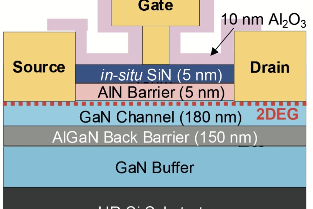
Figure 2. A typical AlGaN/GaN HEMT investigated by the team from the University of Fukui.

Figure 3. Cross-sectional views of three sets AlGaN/GaN HEMTs fabricated on semi-insulating GaN substrates with different mesa depths of (a) 200 nm, (b) 1000 nm, and (c) 1400 nm. The mesa isolation surfaces fall on an undoped GaN channel, an iron-doped GaN buffer layer, and a semi-insulating GaN substrate, respectively.
Due to a lack of availability of high-quality, free-standing native substrates during the infancy of GaN epitaxial research, layers were usually grown on highly-lattice-mismatched foreign substrates, such as sapphire, SiC, and silicon. One downside of this approach is the high lattice mismatch between the GaN epilayer and the substrate. This leads to a high density of defects, which hamper device operation.
Making matters worse, there is a large difference between the coefficient of thermal expansion of the GaN epilayers and that of the foreign substrate. So, when the epiwafer is cooled from its growth temperature of more than 1000 °C to room temperature, the GaN lattice shrinks at a significantly different rate from that of the substrate. This induces a huge stress upon the structure that can lead to bowing of the epiwafer, and even cracking.
To prevent bowing and cracking, thick, complicated buffer structures are inserted between the foreign substrate and the GaN epilayers. A common approach is to add an AlN nucleation layer and a rather thick buffer. However, even with this combination, a high density of threading dislocations "“ typically 108 cm-2 to 1010 cm-2 "“ is generated in the epitaxial layer.
A native platform
A more attractive option, which tackles all these issues head-on, is to grow the GaN epilayer on a free-standing GaN substrate. This is feasible in research laboratories, thanks to advances in GaN growth technology, and it should not be long before it is commercially viable, given the pace of improvement in the production of GaN substrates.
In principle, the absence of material mismatches enables the growth of a GaN epilayer directly on a free-standing GaN substrate. However, in practice, a thin GaN buffer layer is needed to ensure high-quality GaN epitaxial layers (see Figure 2).

Figure 4. (a) Breakdown voltage as function of gate-to-drain spacing for devices with a mesa isolation depth of 200 nm. (b) Two possible leakage components are: leakage through the intrinsic region (blue), and leakage through the extrinsic region (red).
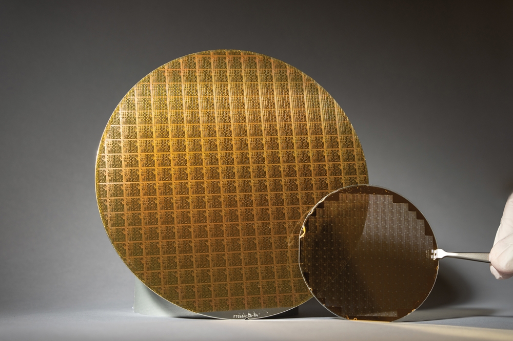
The GaN-based HEMTs that we have used to develop high-blocking-voltage designs feature MOCVD-grown AlGaN/GaN heterostructures. These are formed on 2-inch, free-standing, HVPE-grown GaN substrates with a nominal threading dislocation density of 106 cm-2. To ensure high resistivity of the GaN buffer and substrate "“ this is necessary for good electrical isolation between the devices fabricated on the wafer "“ the GaN substrate and buffer are iron-doped to a concentration of around 1018 cm-3. The iron atoms act as deep acceptors, compensating and reducing residual donor carriers inherent in the grown GaN layers.
In our transistors, the aluminium composition in the topmost AlGaN layer is 20 percent. This produces a strong polarization field in the AlGaN/GaN heterostructure, resulting in a sheet of very mobile electrons, which tend to accumulate in the GaN channel layer very near the AlGaN/GaN interface. This sheet of electrons, called the two-dimensional electron gas, constitutes the channel between drain and source electrodes. This channel can be modulated by an external applied voltage on the gate.
We suspect that the mesa isolation depth impacts the leakage and thus the breakdown voltage. To test this hypothesis, we have fabricated three sets of devices, each with a different value for the mesa isolation depth (see Figure 3). In one set of devices, etched to a depth of 200 nm, the mesa falls on the channel layer; in another, etched 1000 nm, the mesa surface is on the buffer layer; and in the final set, etched to 1400 nm, the mesa surface is on the GaN substrate. For each set, HEMTs were formed with a range of gate-to-drain spacings to determine the critical electric field for the device. With these measurements, we defined the breakdown voltage as the drain-to-source voltage at which the drain current reaches 1 mA/mm, with an applied gate-to-source voltage of -7 V. Note that this bias depletes the two-dimensional electron gas beneath the gate.
For devices with a mesa isolation depth of 200 nm, the plot of breakdown voltage as a function of gate-to-drain spacing can be divided into two regimes: linear and saturation (see Figure 4). In the linear regime, the breakdown voltage increases with gate-to-drain spacing until this reaches 60 mm, indicating that the effective critical electric field in the device is about 0.6 MV/cm. In the saturation regime, the breakdown voltage nears 4 kV for gate-to-drain spacings of around 80 mm or more.
We believe that we can explain this two-regime behaviour with two different leakage currents. One, the leakage through either the active region or the intrinsic region of device, dominates in the linear regime; and the other, leakage through the isolation area or extrinsic region of the device, leads in the saturation regime, when the gate-to-drain spacing exceeds 60 µm. At these longer gate-to-drain spacings, the breakdown voltage saturates, because the parasitic leakage current in the isolation area, which is considered as an area-spreading distributed current component, has a weak dependence on the distance between the electrodes. In contrast, for gate-to-drain spacings of 60 µm or less, the dominant leakage current triggering breakdown runs through the intrinsic region between the gate and the drain. As the gate is close to the drain, leakage is sensitive to the gate-to-drain spacing "“ and as this gets longer, leakage falls, leading to an increase in breakdown voltage

Figure 5. Breakdown voltage as function of gate-to-drain spacing for devices with a mesa isolation depth of 200 nm, 1000 nm, and 1400 nm, where the mesa isolation surfaces fall on undoped GaN channel, iron-doped GaN buffer layer, and semi-insulating GaN substrate, respectively.
It is also worth noting that for devices with a gate-to-drain spacing of 60 µm or less, breakdown is catastrophic, with current surging after reaching the breakdown voltage. But that's not the case for HEMTs with a longer gate-to-drain spacing: they exhibit a soft breakdown, with current slowly increasing as the voltage exceeds the breakdown value.
For our devices that have been etched by 1000 nm to cause the mesa isolation surface to fall on the GaN buffer layer, plots of breakdown voltage as a function of gate-to-drain spacing mirror those with a 200 nm etch (see Figure 5). This suggests that the un-etched GaN channel layer in the isolation area (extrinsic region) does not induce a significant leakage current.
Further etching to a depth of 1400 nm produces a fundamental change in breakdown behaviour. With these devices, which have a mesa isolation surface that falls within the GaN substrate, breakdown voltage increases linearly with gate-to-drain spacing up to 5 kV, and shows no sign of saturation. With these devices, the critical electric field is about 1 MV/cm, which is 70 percent higher than that of the other two sets of devices.
We primarily attribute this increase in the breakdown field to the removal of the iron-doped GaN buffer layer in the extrinsic region. Results suggest that the GaN buffer layer permits leakage through the extrinsic part of the device, most likely through the GaN buffer/ GaN substrate interface. This can lead to premature breakdown.
Higher fields
Although an increase in the effective critical electric field from 0.6 MV/cm to 1 MV/cm is a move in the right direction, but it is still a long way short of the theoretical limit, 3 MV/cm. We have puzzled over this shortfall, and initially thought that our devices were hampered by a leakage current through the underlying "˜semi-insulating' GaN substrate. To test out our theory, we studied HVPE-grown GaN substrates with two different iron-doping concentrations:
1 à— 1018 cm-3 and 9 à— 1019 cm-3. The substrate with higher doping produced a lower leakage current, due to a higher degree of residual donor compensation.
We went on to compare breakdown characteristics by forming ohmic contact pairs with varying distance directly on the surface of both substrates. We found that in both cases the breakdown voltage increased linearly with ohmic-to-ohmic spacing (see Figure 6), and the effective critical electric fields for substrates with iron concentrations of 1 à— 1018 cm-3 and 9 à— 1019 cm-3 were 1 MV/cm and 2 MV/cm, respectively "“ note that 2 MV/cm is the highest ever effective critical electric field reported from a lateral structure. From these results we can conclude that a highly resistive GaN substrate is a key ingredient in the fabrication of a GaN-based HEMT with a high breakdown voltage.

Figure 6. Breakdown voltage as a function of ohmic-to-ohmic spacing of ohmic electrodes formed on top of two different GaN substrates: one, with an iron-doping concentration of 1 à— 1018 cm-3; and another that is heavily compensated, with an iron-doping concentration 9 à— 1019 cm-3.
At first glance it might appear that to realise an even higher effective critical electric field in a GaN HEMT one should start with a highly resistive semi-insulating SiC or sapphire substrate. But this approach is flawed, because growth of a high-quality GaN-based heterostructures demands a more complicated, thicker and leaky buffer, and intermediate layers. It is only the free-standing GaN substrate that can facilitate the growth of very thin buffer GaN layers with controlled high-resistivity properties that are of particular importance for suppressing parasitic leakage current and avoiding premature breakdown.
On a final note, we believe that GaN-based electronic devices will play a very important role in meeting the ever-growing demand for faster, more efficient and "˜greener' technologies. Although these HEMTs are still hounded by some technological issues, we are confident that they can be addressed with a better understanding of the underlying physics. This will, in turn, lead to innovative solutions.