Technical Insight
SOI: A great foundation for the GaN HEMT
Switching the substrate from silicon to SOI increases the RF performance of the GaN HEMT, thanks to a foundation with lower loss and better isolation
BY HSIEN-CHIN CHIU, LI-YI PENG, HSIANG-CHUN WANG AND HOU-YU WANG FROM CHANG GUNG UNIVERSITY, TAIWAN, AND G.-Y. LEE AND JEN-INN CHYI NATIONAL CENTRAL UNIVERSITY, TAIWAN
Thanks to rapid advances in silicon technology, the performance of nanoscale devices for microwave and millimetre-wave integrated circuits is rising fast. However, with silicon, the output power density at millimetre-wave frequencies is limited, while signal loss is significant.
To realise a high output power and a wide bandwidth, the tried and tested solution is to heterogeneously integrate silicon with another semiconductor material on the same substrate.
A common option is to unite silicon with the GaN HEMT. This pairing is capable of producing a high output at high frequencies, due to the wide bandgap of GaN and its capability to handle high power densities. Additional merits of the GaN-on-silicon HEMT are that it can be manufactured at a very competitive cost, and production is scalable, due to the widespread availability of silicon substrates of various sizes.
However, the GaN-on-silicon HEMT has a number of flaws. A significant one is that electrical breakdown occurs vertically through the silicon substrate, due to the large lattice mismatch between the two semiconductors and the comparatively low electrical field strength of silicon "“ it is just 0.3 MV/cm. Another downside is that the best plane of silicon for GaN growth is (111), while the plane for traditional silicon devices is (100); and third significant issue is that the silicon substrate is lossy, especially at radio frequencies, due to its low resistivity and its high loss tangent characteristics.

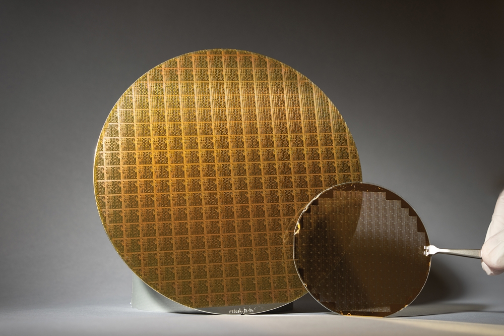
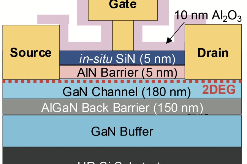
Figure 1. InAlN/AlN/GaN HEMTs are produced on a 6-inch SOI substrate.
To address all these issues several research groups, including our team from Taiwan "“ a partnership between researchers at Chang Gung University and National Central University "“ has turned to the silicon-on-insulator (SOI) substrate as a foundation for the GaN HEMT.
During the last decade, this substrate has proven its capability in commercial applications in harsh environments, where there can be high temperatures and intense levels of radiation; and it has shown its effectiveness at millimetre-wave frequencies, with cut-off frequencies approaching 500 GHz. Another key attribute of the SOI foundation is its high resistivity, which slashes substrate losses in RF integrated circuits. SOI substrates have a higher degree of isolation than those made from silicon, thanks to the oxide layer buried beneath the active region. This design also eliminates substrate noise stemming from crosstalk propagation.
Thanks to all these strengths, in 2004 the SOI trailblazer Peregrine was able to report at the RFIC Symposium that is had used this technology to fabricate RF switches for mobile communication that could contend with power levels up to 35 dBm at frequencies of approximately 2 GHz. Since then, this US chipmaker has ramped production of these SOI devices, which have replaced GaAs pHEMTs as the most common class of switch in handsets.
The strengths of the SOI substrate at high frequencies make it a very promising foundation for producing microwave devices with a high output power density.

Figure 2. The output power of InAlN HEMTs in the microwave spectrum is higher when the devices are formed on SOI than when grown on high-resistivity silicon.
Laying the groundwork for such efforts, in 2013 a team from Hong Kong University of Science and Technology reported the first GaN-based HEMT on a SOI substrate. These transistors exhibited a high breakdown voltage, a low on-resistance, and a reduced vertical leakage "“ three characteristics that are beneficial for switching power device applications.
Our efforts have focused on microwave devices, and involved the use of a silicon (111) handle substrate, which can be used to realize traditional analogue and digital CMOS devices. The first step, SOI substrate preparation, involves bonding a silicon substrate with a (111) crystallographic orientation to the surface of a handle silicon substrate with a (100) crystallographic orientation. This creates a buried SiO2 layer, sandwiched between two silicon crystallographic orientation layers.
Pairing GaN with AlGaN
Armed with this hybrid substrate, we have set ourselves the goal of increasing the operating speed of a GaN-based device. We have selected the lattice-matched InAlN/GaN HEMT, which is one of the most promising alternatives to the conventional, commercial GaN-based HEMT, because it features a strong spontaneous polarization and high carrier mobility.
In addition, the InAlN barrier layers offers a route to reducing strain in the heterostructure, because the InxAl1-xN alloy can be lattice-matched to GaN. This pairing promises superior device reliability to that of AlGaN and GaN, especially in high-voltage and high-temperature environments.
We have fabricated and assessed InAlN/GaN HEMTs that are formed on a 6-inch SOI substrate. Note that this approach parallels efforts in the silicon industry, where complementary MOSFET SOI technology has been applied extensively to the development of microwave and millimetre-wave integrated circuits. In that case, the SOI technology isolates the transistor from the silicon substrate, and allows for stacking, thereby improving circuit power handling and accommodating wide signal swings.
Our InAlN/AlN/GaN HEMTs were produced by MOCVD on a 6-inch p-type (111) silicon SOI substrate with a p-type (100) silicon handle wafer with a thickness of 500 µm (see Figure 1 for a cross-sectional diagram and a scanning electron microscope profile). In this structure, the c-type (111) silicon layer and the buried SiO2 were 5 mm-thick and 0.5 mm-thick, respectively. With this SOI substrate design, heterogeneous integration with silicon (100) CMOS-compatible technology is possible by removing the top material: it could be GaN, (111) silicon or SiO2.
To form our devices, we grew a 2 µm-thick GaN layer on top of a 1.2 µm-thick AlGaN/AlN buffer/transition layer. Increases in the carrier concentration and the mobility of the two-dimensional electron gas resulted from the insertion of a 1 nm-thick AlN spacer layer between the GaN channel and the 10 nm-thick, In0.17Al0.83N Schottky layer. The addition of a 10 nm GaN cap prevents moisture from oxidizing InAlN.
Following device fabrication, we protected the active area of our devices with a low-K polymer material or a photoresist. The rest of the area is etched and removed using an inductively coupled plasma etcher, until the (111) crystallographic orientation of the handle silicon substrate is exposed. At this stage, traditional silicon CMOS devices can be added to the (111) silicon substrate to provide analogue or logic functions.

Figure 3. Reverse recovery characteristics of the InAlN/GaN Schottky barrier diode are better when the device has an SOI foundation, rather than high resistivity silicon. Measurements were made by switching this device from forward (IF = 1 A) to reverse bias (-30 V) with a dI/dt of 60 A/ms.
We performed on-wafer assessments of our HEMTs, which have a 1 µm-long gate, with a common-source configuration, using a PNA network analyser in conjunction with Cascade direct probes. For comparison, we measured an identical InAlN/AlN/GaN HEMT grown on a high-resistivity silicon substrate.
S-parameter measurements revealed a maximum current gain cut-off frequency (fT) of 8.4 GHz and a maximum oscillation frequency (fmax) of 16.3 GHz for our HEMT formed on SOI. In comparison, the equivalent device on high-resistivity silicon has an fT of 6.3 GHz and an fmax of 12.1 GHz. We attribute the higher frequencies of the SOI-based device to a higher peak transconductance and a smaller loss tangent behaviour associated with the substrate.
The power of SOI
The microwave load-pull power performance of our InAlN HEMTs has been evaluated at 0.9 GHz and a drain bias of 12.0 V. The device on SOI produced a saturated output power of 24.6 dBm and a power-added efficiency of 50.2 percent. In comparison, the figures for the HEMT on high-resistivity silicon were 23 dBm and 35.2 percent (see Figure 2).
The increase in the power-added efficiency for the HEMT grown on SOI is due to a combination of a lower leakage current and a higher fmax. Thanks to the lower substrate-induced lateral leakage, the saturated output power of the InAlN HEMT on SOI was higher, especially at high drain-source voltages.
We have also evaluated the potential of our device for power switching applications, by forming a Schottky barrier diode on our InAlN HEMT on SOI. This device shows reverse recovery characteristics when switched from forward to reverse bias, due to the parasitic capacitance of the Schottky diode (see Figure 3).
The magnitude of the reverse recovery charge depends on several factors: the diode junction capacitance, the concentration of deep levels in the bandgap, and the parasitic capacitance shunt to the Schottky diode. The device grown on SOI has a lower reverse recovery charge than that grown on high-resistivity silicon (see inset in Figure 3 for details), thanks to a reduction in the concentration of deep levels in the bandgap.
Our work shows that SOI substrates deliver significant benefits over high-resistivity silicon, including superior electrical characteristics, such as higher operating frequencies, greater load-pull powers and smaller reverse recovery charges. All these characteristics benefit from the reduced stress associated with SOI substrates.
However, the InAlN HEMT on the SOI substrate still requires considerable refinement. Although SOI trims substrate capacitance and lowers crosstalk noise, thanks to the presence of the buried-oxide, this thick subterranean layer increases self-heating in the InAlN HEMT and the Schottky barrier diode. To address this, packaging is needed to provide superior thermal management. A second significant issue is that although the SOI substrate can reduce growth stress compared to the traditional silicon substrate, it is challenging to control the bowing of the substrate during GaN film growth.
Both these issues are not insurmountable, however, and InAlN devices on SOI substrates have a bright future as reliable, high-speed and high-power electronic devices.