Technical Insight
Reducing initial failures in GaN-on-GaN vertical diodes
Eradicating epi-layer growth pits in GaN-on-GaN diodes boosts yield by reducing failures associated with low breakdown voltages
BY FUMIMASA HORIKIRI FROM SCIOCS


The GaN semiconductor device market is on the rise. GaN-on-SiC devices are gaining traction in RF applications, such as cellular base stations, and power devices based on GaN-on-silicon are starting to make a commercial impact.
However, although both of the devices are better than their silicon rivals, they are not optimal for GaN. That's because they are hampered by their lateral structure, which is formed by hetero-epitaxial growth of GaN-based layers on SiC or silicon substrates.
A far more promising architecture is that of the GaN-on-GaN vertical device. It has the potential to form a key component in highly efficient power-conversion systems by combining an extremely low specific differential on-resistance with a high breakdown voltage.
At SCIOCS, which was formed in 2015 and has Sumitomo Chemical as the 100 percent shareholder, we have underlined the capability of this vertical chip by developing a very impressive GaN p"“n diode. This device, formed on a freestanding GaN substrate by void-assisted separation, combines a record-breaking blocking voltage of 4.7 kV with an on-resistance of just 1.7 mW cm2.
To convert the record-breaking device into a great commercial success, it has to be manufactured in high volume with a good yield. But that's currently challenging on two fronts: there is a lack of availability of large GaN substrates; and the device epilayers are plagued with a high density of pits, which lead to low breakdown voltages. We are tackling both these issues head-on "“ we are developing larger GaN substrates, which are formed with a novel tiling approach; and we are introducing better growth conditions that slash the epi-pit density.
Building bigger wafers"¦
For the production of GaN devices on freestanding GaN substrates, wafer size is a far bigger issue than it is for the manufacture of lateral GaN devices on SiC and silicon. For freestanding GaN, commercially available substrates have diameters of just 2"“4 inches. These small sizes impact the cost of the GaN-on-GaN devices, and when larger wafers are used, there is greater strain and deviation along the c-axis.
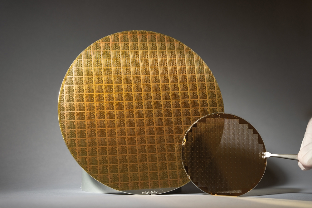
One way to overcome these issues is to produce far larger wafers with a tiling technique (see Figure 1). By using HVPE to join multiple hexagonal-seed, void-assisted-separation GaN substrates, we have produced 7-inch GaN substrates. They have a variation along the c-axis direction that is no more than that of the conventional, smaller substrates.
Figure 2. Vertical GaN-on-GaN, p"“n and p"“i"“n diodes require thick epitaxial layer to achieve a higher breakdown voltage. The double and triple drift-layer structures provide a low on-resistance in combination with a high blocking voltage.
Material quality of this 7-inch substrate is very high. The dislocation density is uniformly less than 2 à— 106 cm-2, except in the connecting regions, which account for only about 0.2 percent of the area of entire substrate.
For this 7-inch substrate, hexagonal tiles have been employed to maximize the area-taking efficiency of 2-inch substrates. However, if it is important to match the pitch with dicing lines, square seeds can be tiled to make a larger substrate.
"¦ and better diodes
The other main issue that we have addressed, yield, arises because of the very thick epitaxial layers in vertical GaN-on-GaN devices. For lateral structures, such as GaN HEMTs, epilayers are just 1"“2 µm thick. But for vertical structures, they can be between 20 times and 40 times as thick, in order to realise a sufficiently high blocking voltage. For example, for GaN-on-GaN p"“n and p"“i"“n diodes with blocking voltages between 2 kV and 5 kV, epilayers in simple vertical devices are between 15 mm-thick and 35 mm-thick (see Figure 2).
In these devices, which are grown by MOCVD, there is a lightly silicon-doped n--GaN layer underneath a p-GaN layer. As the drift layer in these devices is relatively thick, the diode's on-resistance is higher than ideal. A major challenge with vertical GaN diodes is to prevent the on-resistance from getting too high, while realising a high breakdown voltage without sacrificing the on-resistance.
Figure 3. Increasing the breakdown voltage of small chip, GaN-on-GaN diodes leads to an increase in the specific on-resistance.
To address this particular challenge we turn to a multi-drift-layer structure. Armed with a graded silicon-doping depth profile, we have found that it is possible to reduce on-resistance while maintaining a high blocking voltage with a moderate n--GaN drift-layer thickness. With our particular design, devices with a low on-resistance can withstand blocking voltages of 2"“5 kV. The high performance of our device is demonstrated in Baliga's figure of merit. Its value, which equals the square of the blocking voltage, divided by the on-resistance, exceeds 10 GW cm-2 (see Figure 3). Such a high figure stems from the GaN-on-GaN vertical structure.
One of the issues associated with the growth of vertical GaN structures on native substrates is the substantial increase in material deposited on the reactor wall. Due to the requirement for thick epilayers, a substantial amount of GaN is formed on the wall, leading to the deposition of many particles on the substrate. This is detrimental, because particles cause devices to fail, due to their low breakdown voltage.
These particles, which cause epi-layer growth pits, may be seen when using a microscope to scrutinise the surface of the GaN layers of vertical diodes (see Figure 4). We have used photoluminescence mapping of the epilayer to expose the identity of these particles − they produce yellow luminescence that corresponds to a deep level of GaN, such as a carbon or gallium vacancy. Cross-sectional imaging of an epi-substrate interface provides further insight, revealing that the GaN particles are the origin of the corresponding epi-layer growth pits.
Further evidence for particles causing detrimental epi-pits comes from time-of-flight secondary-ion mass spectrometry. This technique, which is capable of a high spatial resolution, indicates the presence of an impurity at the bottom of the epi-pit. This imperfection contains high levels of silicon and oxygen, which both act as donors in the n-GaN layer on the substrate (see Table I).
Electrical measurements add further weight to our claim that the epi-pits are a yield killer in vertical p"“n diodes. Current-voltage plots show that 2 kV p"“n diodes with pits on their 200 mm electrodes have a breakdown voltage of just 50 V, while those without pits provide the intended blocking voltage (see Figure 5). Note that a breakdown voltage of just tens of volts can be accounted for by assuming that the palladium electrode is in direct contact with the n-type GaN substrate, which has a carrier density of 2 à— 1018 cm-3.
Forward current-voltage characteristics for both types of diode are markedly different. Those without pits possess ideal rectifying properties (their ideality factor is 2), whereas those with pits have a high leakage current, even at low forward bias. These results reveal that pits form additional parallel circuits, in the form of Schottky barrier diodes.
We have evaluated device yield − an important issue for power applications "“ with a combination of current-voltage measurements and optical microscopy. These efforts involved a study of a series of p"“n diodes with various electrode sizes: for example, electrodes 100 µm, 200 µm, 400 µm, and 800 µm in diameter. This allowed us to determine whether there is a direct correlation between the device yield and the epi-pit (if it is, yield is a function of electrode size). We found that measured yield depends on the electrode's size in a manner that confirms that epi-pits are fatal to the initial properties of GaN-on-GaN diodes.
Figure 4. A combination of microscopy and photoluminescence can identify the yield-killing epi-pits in the GaN-on-GaN diodes. The micrograph shows a GaN particle and the corresponding epi-pit, while photoluminescence mapping of the yellow luminescence shows the deep levels of the GaN. The photoluminescence mapping of the band edge shows that the pit has a high concentration of carriers. The cross-sectional image indicates that the particle has induced the formation of the epi-pit.
Table I. Time-of-flight secondary-ion mass spectrometry results around an epi-pit.
To reduce the density of these killer defects, we have optimized the cleaning of the reactor, the pre-cleaning of the GaN substrate, and the growth conditions. This enabled the production of pit-free GaN-on-GaN wafers with an epi-pit density of less than 0.2 cm-2 (see Figure 6).
This low epi-pit density addresses issues associated with the yield of large-sized, vertically structured GaN-on-GaN power devices, which have a strong future ahead of them, thanks to their great performance and the development of larger GaN substrates. Over the next year or so, we will aid the commercialisation of these GaN-on-GaN epiwafers by improving the epi growth process.
Following the eradication of epi-layer growth pits, we will go on to improve the epi quality. This should lead to a reduction in electron-trap density and an increase carrier life-time. We also plan to investigate the influence of the substrate off-angle deviation on the dislocation density, which may affect the uniformity and the reliability on vertical GaN-on-GaN devices.
Figure 5. Reverse current-voltage characteristics of various 2 kV p"“n diodes shows that epi-pits lead to a dramatic reduction in breakdown voltage. The inset shows forward current-voltage characteristics of p"“n diodes with and without pits. The micrographs show diodes without the field plate. The size of the pits was approximately 15"“20 mm.
Figure 6. Yield of p"“n diodes calculated with the equation Yield= exp(-DAS), where D is the density of killer defects in cm-2, A is the device size in cm2, and S is the ratio of the defect-sensitive area. The experimental data were obtained from the yield of p"“n diodes for electrode diameters of 100 mm, 200 mm, 400 mm and 800 mm. The density of killer defects was assumed to be 20 cm-2. This density correlates well with the pit density measured by optical microscopy. A recently produced epitaxial layer showed a pit density of less than 0.2 cm-2.


