The third dimension: The logical step for III-Vs
Traditionally, one of the benefits of trimming the size of the silicon transistor has been a cut in the power it consumes. But that's no longer the case, and due to this, there is a great deal of concern over how to handle the power consumed by the transistor, and also the interconnects.
BY SANGHYEON KIM, SEONGKWANG KIM AND HYUNG-JUN KIM FROM KOREA INSTITUTE OF SCIENCE AND TECHNOLOGY
To try and address these issues, researchers in industry and academia have been developing transistors with high mobility channels made from III-Vs, such as InGaAs, GaSb; and also germanium. Turning to these materials allows electrons and holes to zip along at far faster speeds than they would do in silicon, increasing the drive current. Thanks to this, is possible to reduce the voltage supplied to the transistor and ultimately its power consumption.
However, that's not the only lever to pull to cut power consumption. In addition, transistors can be stacked vertically and monolithically, an approach called monolithic 3D (M3D). Switching to this architecture shortens the length of interconnects, cutting delay and power loss; and it increases transistor density, allowing ultimate power scaling. What's more, the M3D architecture enables functional scaling, because it allows the integration of non-digital components, such as RF devices and sensors.
Figure. 1 Monolithic 3D integration in silicon is challenging, due to incompatible process temperatures. This issue can be overcome by turning to III-V semiconductors.
One of the biggest challenges currently facing silicon-based M3D technology is associated with the incompatible process temperatures (see Figure 1). A low-temperature process is essential for fabricating the top transistors, but current CMOS technology requires a high process temperature, typically 1000-1100 °C. This is hot enough to melt the interconnect metal above the bottom transistor and severely degrade the performance of the bottom transistor "“ it is formerly fabricated prior to the production of the top transistor. Due to this severe thermal budget constraint, undertaking M3D integration with conventional silicon technology is very difficult.
Keeping cool with III-Vs
With III-Vs this problem is avoided. Transistors with these channel materials have a process temperature that is typically below 400 °C, which is low enough to prevent damage to bottom transistors and interconnect metallization.
Recently, there have been many reports of high-performance InGaAs-on-insulator MOSFETs. These devices are highly scalable, and they have a very straightforward device structure, which makes them promising candidates for M3Ds. However, there is a stumbling block: an exorbitant increase in cost compared with that for silicon processing. From a manufacturing perspective, this outweighs all the benefits associated with using InGaAs.
To address this shortcoming, our team at the Korea Institute of Science and Technology (KIST) in Seoul has recently developed cost-effective processes for fabricating InGaAs-on-insulator substrates, and using them to make high-performance MOSFETs. At the heart of our technology are the direct wafer bonding and epitaxial lift-off techniques used to form InGaAs layers on silicon substrates (see Figure 2). A key advantage of this process is non-destructive wafer splitting, which enables donor wafer re-use.
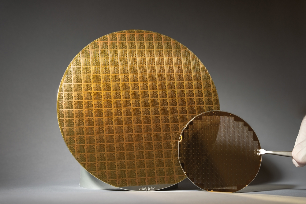
Figure 2. Researchers at KIST are processing InGaAs-on-insulator wafers by wafer bonding. This multi-chip/-wafer bonding process is applicable to wafers with diameters of 300 mm or more.
Device formation begins with the epitaxial growth of InGaAs active layers on InP substrates. Sandwiched between the active layers and the substrate is an AlAs sacrificial layer. Controlling its thickness is crucial: it impacts layer quality, due to the lattice mismatch between InP and AlAs, and it also governs the speed of the epitaxial lift-off process. Experiments on structures with various AlAs thicknesses allowed us to determine the optimum thickness for this layer.
Our next step is to deposit a Y2O3 layer on the III-V epi-wafer and the silicon wafer. The former has been prepared for a speedy epitaxial lift-off with a pre-patterning process that includes enlargement of the exposed etching area. One of the keys to enhancing the speed of the epitaxial lift-off is to use a hydrophilic surface, such as InP, rather than GaAs or InGaAs. This type of surface ensures a smooth solution flow and prevents large reaction products.
Once a Y2O3/InGaAs/AlAs/InP and a Y2O3/silicon substrate have been bonded together, the resultant structure is etched in HF solution to remove the AlAs layer and yield an InGaAs-on-insulator/silicon substrate and an InP donor wafer. This process typically takes an hour, making it the fastest epitaxial lift-off technique reported so far. Following this step, the InGaAs-on-insulator wafers are used to fabricate the MOSFET, while donor substrates are re-used for further epitaxial growth, enabling significant cost reductions.
Figure 3. Cross-sectional transmission electron microscopy of InGaAs/Y2O3/silicon, and high-resolution images of the sample. Clear bonding behaviour is observed, with no evidence of distinguishable bonding interfaces.
Characterising these wafers reveals the good crystal quality of our material, and its clear bonding behaviour. These attributes are seen in our transmission electron microscopy images (see Figure 3), and demonstrate the capability of our process for providing high-quality InGaAs films on insulator that are essential for M3D technology.
Forming FETs
We are the first team to ever fabricate InGaAs-on-insulator MOSFETs on a silicon substrate using direct wafer bonding and epitaxial lift-off. Our transistors were formed using a recessed gate structure and a Y2O3/InGaAs MOS interface. Ensuring the high mobility in the device is the combination of direct wafer bonding and epitaxial lift-off processes. They lead to good layer quality, and a dedicated thermal annealing that improves the MOS interface of Y2O3/InGaAs.
Our results are encouraging. The trap density at the MOS interface is about 5 x 1011 cm-2 eV-1, which is nearly a record, and is an order of magnitude below the typical figure for a high-k/InGaAs interface. Devices have good electrical properties, such as an on/off ratio of 106, a sub-threshold swing of just 120 mV/dec, and a peak mobility of approximately 2800 cm2 V-1 s-1, which is a record for surface channel In0.53Ga0.47As MOSFETs (see Figure 4).
Note that the mobility of our InGaAs-on-insulator MOSFET exceeds that of InGaAs MOSFETs on InP substrates. We believe that this superiority may stem from the high layer quality, and also the more favourable charge distribution in the channel layer. Even better results may follow, through further oxide thickness scaling, interface improvement, and the optimisation of the entire process.
Figure 4. (a) The mobility characteristics of MOSFETs produced from InGaAs-on-insulator are very similar to those from bulk InGaAs. (b) Benchmarks of mobility as a function of equivalent oxide thickness (EOT)/capacitance effective thickness (CET) for surface-channel, In0.53Ga0.47As MOSFETs.
Re-using the subs
The low cost of our process results from the fast epitaxial lift-off and the re-use of the donor wafers. Note that for many III-V devices, their high cost comes from the high price for the native substrate, which is much more than that for silicon.
To investigate the extent of re-usability of our InP donor wafers, we mimicked the epitaxial lift-off process by growing InGaAs and AlAs layers on InP, etching these structures in H3PO4-based solutions, and then undertaking re-growth. According to atomic force microscopy, the smooth surface found on a fresh InGaAs MOSFET epistructure is also present on a re-used wafer (see Figure 5 (a)). This indicates that an epi-ready InGaAs surface may be maintained after wafer re-use.
Since surface morphology is no guarantee of re-usability, we also compared the electrical characteristics of InGaAs MOSFETs from fresh and re-used wafers. Encouragingly, the mobility characteristics of the two types of device were almost identical, indicating that the donor wafer can be re-used after the epitaxial lift-off process (see Figure 5 (b)). This verifies our approach to slashing the cost of producing InGaAs-on-insulator transistors. The upshot is a route to: cost-effective M3D architectures that benefit from an insulation layer, which eases integration; and the production of next-generation logic circuits featuring high-quality InGaAs layers.
Figure. 5 (a) Atomic force microscopy of InGaAs surfaces grown on fresh and re-used InP wafers. Both surfaces have a low root-mean-square roughness. (b) The mobility characteristics of InGaAs MOSFETs on fresh and re-used substrates are very similar.
Our approach is one of several that can unite III-Vs with silicon. Its rivals include a wafer bonding process that involves the etch-out of donor substrates, aspect ratio trapping, and confined epitaxial layer overgrowth. Comparing all these, we believe that our technology has much to offer from a viewpoint of device engineering and cost reduction (see Table 1), while offering the opportunity to develop stacking technology that allows the integration of other classes of device, such as sensors, lasers and energy harvesters.


