The monolithic integration of GaN

Combining trench isolation with silicon-on-insulator technology enables monolithic integration of fully isolated power devices
BY KAREN GEENS, MARLEEN VAN HOVE AND STEFAAN DECOUTERE FROM IMEC
GaN is destined to revolutionise the power semiconductor industry. It is tipped to displace the traditional silicon-based power chip, thanks to its higher breakdown strength, faster switching speed, higher thermal conductivity and lower on-resistance.
Development of this technology began with lower-voltage DC-DC converters and high-voltage (600 V) power-switching applications. Due to this, first-generation GaN-based power devices are going to play a key role in power conversion within battery chargers, smartphones, computers, servers, the automotive industry, lighting systems and photovoltaics.
GaN power devices are not grown on native substrates, which are pricey and limited in availability. Instead, various alternatives are employed, with sapphire, SiC and silicon the most popular. The latter's appeal is its cost, allied to the opportunity to use larger wafer diameters "“ 200 mm or more "“ and run the material through standard semiconductor processing lines.
Today, most GaN power systems are formed from multiple chips. GaN-based components "“ or devices, such as HEMTs "“ are assembled as discrete components, before they are united on a printed circuit board.
The downsides of this approach are that it is complex and expensive. A better option is to monolithically integrate GaN power devices on a single chip, because this yields a lower-cost, simpler system. What's more, monolithic integration promises better control of parasitic capacitances and inductances, and a superior power conversion efficiency.
A typical example of a convertor topology that would benefit from monolithic integration is a half bridge "“ it is one of the most common switch circuit topologies used in power electronics today. A half bridge consists of a low-side switch (with the source at a low potential), and a high-side switch (with the source at a high potential). The pair of switches are connected in an electrical circuit and turned on and off in a complementary fashion during operation. So the switches have to be biased differently, which requires isolating high-side and low-side devices.
Realising this is far from easy with GaN-on-silicon. If lateral isolation is adopted, different components must be separated by an isolation implant or mesa etching; and if vertical isolation is pursued, partially realisation is possible with a high-resistive buffer. Note that with the latter topology, devices still share a common conductive silicon substrate, which can only be referenced to a single potential at a time.

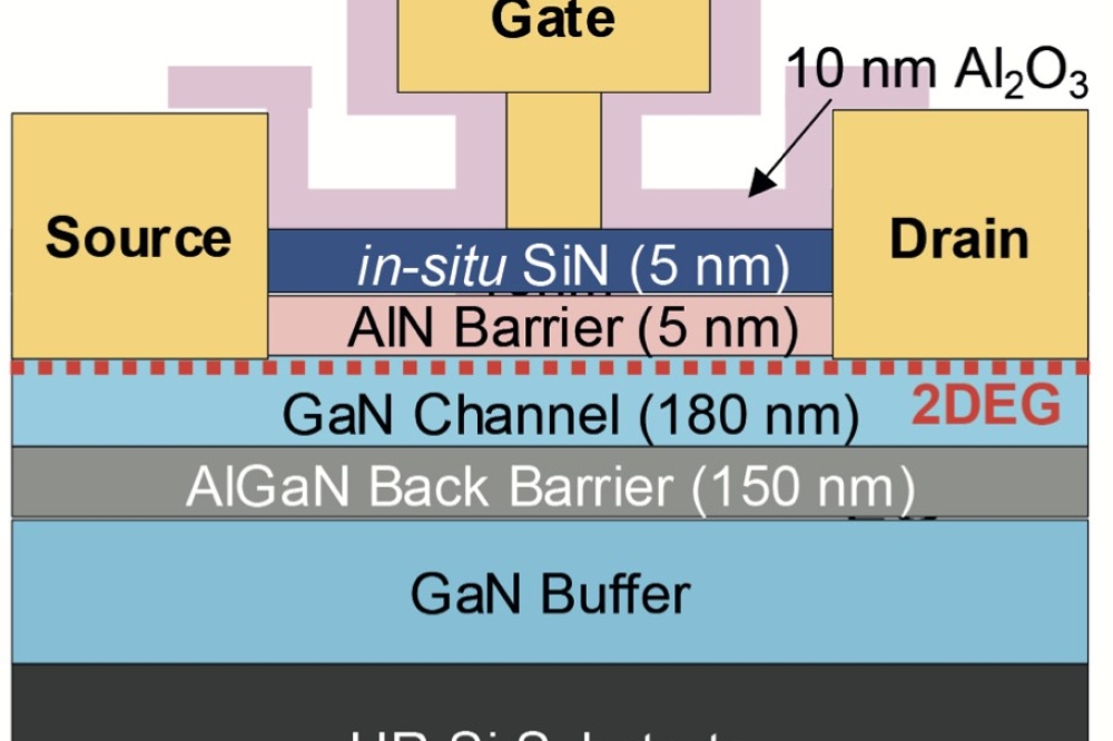
Figure 1. The architecture of imec's E-mode p-GaN HEMT.
An SOI solution
At imec of Leuven, Belgium, we are breaking new ground by isolating devices through growth on silicon-on-insulator (SOI) wafers, followed by trench isolation. SOI wafers contain a layer of SiO2, sandwiched between two layers of silicon. This composite, designed to improve insulating characteristics, is used in the silicon industry to try and improve performance at the nanoscale.

Figure 2. Top view of an imec device. A box-like isolation structure is created around each HEMT.
That's not the only use of SOI, however "“ many teams, including our own, are investigating its potential as a foundation for improving the crystal quality of GaN. It is not trivial to switch from silicon to SOI for GaN growth, however: there are more layer parameters to tune, such as the thickness of the silicon (111) layer and the compliant SiO2 layer; and dedicated strain engineering is required to control stress during epitaxy.
By turning to SOI, we can isolate devices by trench etching through GaN and silicon and into the SiO2 buried layer. Ultimately, that has enabled us to demonstrate the monolithic integration capabilities of GaN-on-SOI technology, such as its use in half-bridge circuits. To form this circuit, we use enhancement-mode (E-mode) p-GaN HEMTs: they have a p-type gate and operate in normally off mode. That method of operation is preferred to normally on for power efficiency and fail safety.

Figure 3. (a) Horizontal breakdown of the trench isolation and (b) vertical breakdown of the SiO2 buried layer on the 200 mm GaN-on-SOI at 25°C and 150°C.
Fabrication of our monolithic, GaN-based circuits begins with MOCVD of a GaN epi-stack on a 200 mm SOI wafer "“ a structure with a layer of silicon (111), on top of SiO2 and silicon (100). Epitaxial growth adds an AlN nucleation layer, followed by an (Al)GaN buffer layer, a GaN channel layer, an AlGaN barrier layer and a magnesium-doped p-GaN layer.
To control the stress built up in the wafer during growth, we undertake delicate strain engineering. This enables production of a GaN-on-SOI wafers with a controlled warpage and good mechanical strength. E-mode p-GaN HEMTs are formed, using a TiN/p-GaN stack for the gate.
Horizontal and vertical isolation of the HEMTs is realised with a combination of nitrogen implantation isolation and etching of a trench through to the SiO2 buried layer. A box-like isolation structure results, with HEMTs surrounded on all sides by an insulating dielectric (see Figures 1 and 2).
Our p-type GaN HEMTs have been fully qualified for 200 V switching applications. Both the horizontal breakdown voltage of the trench isolation, and the vertical breakdown of the SiO2 buried layer, are typically as high as 500 V at 150°C (see Figure 3).
Benefits of device isolation are highlighted by the transfer characteristics of our GaN-on-SOI HEMT (see Figure 4). With this foundation, transfer characteristics undergo very little change when the substrate of the neighbouring device is biased between -200 V and 200 V. In stark contrast, when this occurs on a silicon substrate, transfer characteristics shift, highlighting performance degradation in these devices.

Figure 4. Transfer characteristics of a HEMT at 150°C (a) with a common silicon substrate biased from -200 V to 200 V (GaN-on-silicon) and (b) while simultaneously biasing the neighbouring silicon (111) HEMT layer at different voltages (GaN-on-SOI).
Our results reveal, for the first time, that the combination of GaN-on-SOI and trench isolation is a promising approach to monolithically integrate GaN power systems on the same wafer. Our next steps will be to study the thermal performance of GaN-on-SOI, and to optimise the composition of the SOI substrate and the GaN epitaxial stack. In addition, we will move to higher levels of monolithic integration, and increase the operating voltage to 650 V. Figure 1. The architecture of imec's E-mode p-GaN HEMT.