Power electronics: Easing the use of GaN

Simplifying a desinger's life with a process design kit for GaN-based integrated circuits
BY Nick Fichtenbaum FROM Navitas Semiconductor
Not that long ago, designers of power systems had no choice over the material in their components: it had to be silicon. Recently, however, they have had their interest piqued by the promising properties of GaN. The appeal is that discrete FETs, in either the form of cascoded depletion-mode (D-mode) devices or enhancement-mode (E-mode) variants, have the potential to deliver a superior performance at the individual component-level.
Unfortunately, theory is not borne out in practice. The "˜real world' has various system challenges, including vulnerable gate drive, level-shifting, parasitic impedances and complexity. All increase cost and risk, while reducing switching speeds and impairing power density benefits.
Due to these issues, designers that are under-pressure "“ and that is the norm "“ tend to desert the new-fangled wide band-gap devices and retreat to their comfort zone: silicon FETs, serving in low-frequency circuits. However, that doesn't have to be the case. Thanks to efforts by our team at Navitas Semiconductors of El Segundo, CA, power designers can enjoy the benefits of GaN by turning to the industry's first GaN power IC Process Design Kit (PDK). It allows monolithic integration of GaN IC circuits with GaN FETs.

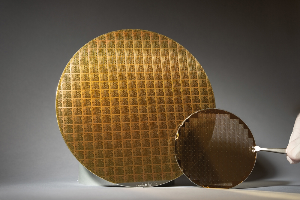
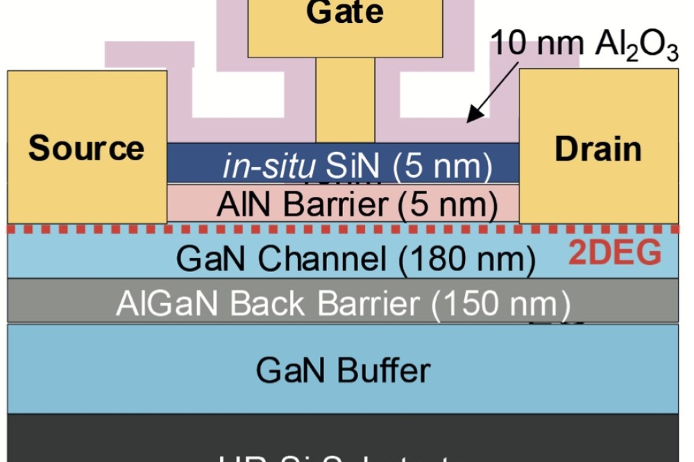
Figure 1. Lateral GaN-on-silicon devices feature a two-dimensional gas that enables high channel mobility and a low resistance.
Different architectures
Lying at the heart of every GaN FET is a two-dimensional electron gas, formed at the GaN-AlGaN interface (see Figure 1). This gas creates a very high mobility in the channel and drain drift region, leading to a far lower resistance than that for devices made from silicon or SiC.
Devices made from GaN can withstand high electric fields. This allows depletion regions to be very short or narrow, and devices to operate at high carrier densities while being packed very densely.
For the GaN FET with a lateral architecture, devices with a rating of 650 V can typically handle more than 800 V. In this FET, the drain drift region is 10-20 mm thick, so the field strength is around 40-80 V/mm. This is well above the theoretical limit of silicon that is about 20 V/mm, but still well short of the bandgap limit for GaN, which is about 300 V/mm. So there is substantial room for improvement for the lateral GaN FET.

Figure 2. The AllGaN is the industry's first GaN Power IC process design kit, according to its developer, Navitas. It can be used to form (a) single and (b) half-bridge circuits, and (c) packaged devices.
Better results may be possible with vertical GaN FETs. In terms of development, they lag their lateral cousins, being held back by the need for epilayer growth on bulk GaN substrates. This foundation is very expensive, and predominantly limited to diameters of 3-inch or less.
Additional challenges facing vertical GaN are: the need to win share from the more established SiC FET market; and that the lateral E-mode (normally off) GaN device can now be produced on 150 mm production-quality GaN-on-silicon wafers using existing foundry processes. The latter breakthrough opens the door to manufacture of high-volume, cost-effective switches and power ICs.
Production of FETs that are E-mode, rather than D-mode, is a big deal. Development of these transistors began with D-mode, with devices kept in an off-state through pairing with a silicon FET in "˜cascode' configuration. That's not a good solution "“ it increases packaging inductance and cost.
Early E-mode FETs addressed this issue, but they had vulnerable gates and a very low threshold voltage. Due to this, they were susceptible to noise and voltage spikes that stemmed from the surrounding switched-mode converter circuit. The upshot was that E-mode devices required complex, expensive control and gate drive circuits. That solution held back the high-frequency performance of the GaN switch to the point where there is minimal, if any, advantage over silicon. With a small edge at best, market adoption is limited.
We overcome these issues and unlock the potential of the GaN FET via the integration of lateral device structures. Power designers that adopt our AllGaN, which is the industry's first GaN power IC Process Design Kit (PDK), benefit from monolithically-integrated 650 V GaN FETs with GaN IC circuits, including those with drive and logic functions.
The proprietary AllGaN PDK is remarkable, given its restricted device-level tool-set, which includes the absence of p-channel devices and diodes. For this monolithic integration technology, which is impossible to realise using vertical GaN, D-mode GaN and SiC technologies, we have 30 patents that are granted or are pending. They are covering the device, packaging and application/system innovations.}

Figure 3. A 1 MHz half-bridge topology using Navitas GaN Power ICs.
The "˜ideal switch'?
We know that we need to convince frustrated, skeptical power designers of the capability of our technology. How are we able to remove risks, complexity and speed limits, so that we can give these engineers performance and confidence, and ultimately enable them to deliver the next-generation of power converters? Well, the answer is to revisit the concept of the "˜ideal switch', and see how well our GaN power ICs perform. Here they deliver a high-performance, easy-to-use, rugged, digital-in, power-out building block. It is clear that the days are numbered for the normally-on, D-mode GaN FET. It is compromised by its multiple die and highly-inductive, costly packaging.
E-mode parts operating from 80 V to 650 V have now been qualified to JEDEC standards, allowing these lower cost, higher-speed devices to open new circuit possibilities. But there is one major caveat: exposed GaN gates are vulnerable, so designers must carefully control voltages and system noise, while using dedicated discrete or co-packed drivers, voltage regulators and level-shifters. This adds to component count, size, cost and complexity.
Problems associated with the vulnerable gate of discrete GaN are avoided with our GaN power ICs. The combination of monolithic on-board voltage regulators and high-speed drivers directly and carefully feed the GaN gate with no parasitic impedance, no voltage spikes, no false turn-on and no external exposure.

A multi-project wafer (MPW) or "˜pizza-mask' at probe test
With AllGaN technology, we exploit the fundamental lateral capability of E-mode GaN, to integrate multiple device structures on a single, monolithic die. This enables a GaN Power IC to be created with a high supply voltage of 30 V, and simple, logic input.
The capability of monolithically-integrated circuits is clear in the waveforms they produce. They have a true "˜text book' feeling with very clean rising and falling edges, no ringing, and extremely fast turn-on and turn-off propagation delays (see Figure 3). Integration eliminates gate overshoot and undershoot, while zero inductance on-chip ensures no turn-off loss.
This lack of ringing/overshoot simplifies tight control of deadtime in half-bridge circuits. This very fast, incredibly quiet switching performance, combined with an integrated gate drive and simple PWM input, enables the design of a variety of different high-frequency power converters, raising practical speeds more than ten-fold. No more are they limited to 65 kHz, or 100 kHz "“ now more than 1 MHz is possible.
Housed in industry-standard, low inductance, surface-mount QFN packaging, our GaN Power ICs provide high-performance, low-cost circuits with the highest power density. A digital input offers flexibility in design. The GaN devices can be placed on the main board, or positioned on the daughtercard, close to or far from the control IC.

Figure 4.VCC operating current (IQCC-SW), as a function of operating frequency (FSW), for a Navitas 160 mΩ GaN Power IC.
One key concern for the circuit designer is the area of the printed circuit board. Our GaN half-bridge power IC "“ incorporating all functions, including powertrain "“ excels in this regard, delivering a 20-fold reduction in area compared to silicon-based alternatives.
Another strength of our approach is its ability to handle fast-moving voltage waveforms. This is getting more important as system switching frequencies increase to take advantage of GaN and slew-rates rise correspondingly. With our AllGaN technology, changes as fast as 200 V/ns are possible.
There are additional safety features associated with lateral integration, which are not possible for discrete devices. If FETs are discrete, they are not rated for electrostatic damage (ESD), as they don't have any ESD structures. In contrast, our GaN power ICs technology can create ESD diode structures that are capable of withstanding 1 kV. We can also incorporate topology-related protections, such as undervoltage-lockout and shoot-through protection, to ensure robust circuit performance.
One of the merits of integration is a greatly-reduced component count. Simplified designs have fewer interconnects and thus increased reliability. By constructing circuits on a single, heterogeneous AllGaN platform, variation in system parameters is small. This reduces the chance of disparate component/technology interactions or wide, worst-case application parameter distributions.

Figure 5. A Navitas 150 W AC-12 VDC reference design at 21 W/inch3 (uncased). This features CrCM PFC and LLC topology.
Digital in, power out
As already stated, our GaN power ICs have simple logic PWM inputs "“ either 3.3 V, 5 V or 12 V signals "“ that are produced by industry-standard, low-cost, low voltage "˜no driver' control ICs, such as ASICS or DSPs. Due to the natural low-charge structure of GaN, combined with careful driver design, the input current consumption is small, rising only slightly with frequency. For example, at 15 V, the quiescent operating current for a 160 mW single GaN power IC increases from a mere 0.9 mA at 10 kHz to only 1.1 mA at 1 MHz. That's a rise of only 20 percent for an increase in switching frequency of two orders of magnitude.
Designers that select our half-bridge GaN Power ICs also benefit from the elimination of external analog elements, like the bootstrap charging diode and expensive level-shifter/drivers. All they need to do is simply drive the two, low-side referenced PWM inputs directly from the controller.
The effectiveness of the powertrain is governed by the performance of the overall system. To fulfil the Department of Energy's Level VI requirements, benchmarks must be met for average efficiency and standby-power, plus statutory requirements for the likes of EMI, PFC and safety compliance. Note that the benefits of higher efficiency include the use of low case temperatures, while the low standby-power requirements can be met by enabling / disabling the GaN power ICs in burst-modes. Once efficiency and standby-power are addressed, circuits can operate at higher frequencies, allowing the use of new high-frequency magnetic materials for higher power density.

Figure 6. A Navitas 45 W ACF at 25 W/inch3 (uncased).
AllGaN's technological capability is demonstrated by measurements on AC-DC power converters. These results don't tell the whole story, however, because GaN Power ICs are rated at 2 MHz or more, while commercially available control ICs are currently limited to typically 300-400 kHz. This situation is set to change, with high-frequency controllers in development that will exploit GaN's fundamental high-frequency capability.
The first of our two examples involves the use of single GaN Power ICs in a 150 W, AC to 12 V DC converter (see Figure 5). It delivers a power density of 21 W/inch3, and higher values should be possible following more optimisation by power designers. Efficiency reaches 95.6 percent, and there is a very controlled, quiet EMI spectrum, thanks to a soft-switching, no-overshoot topology.
Our other example involves the use of a half-bridge GaN Power IC in the soft-switching active clamp flyback topology of a 45 W, AC to 20 V DC adapter. Here, the active clamp flyback realises a power density of 25 W/inch3 while delivering 93 percent efficiency at the critical 90 VAC input point "“ this is where currents are highest, so thermal performance takes its biggest hit.
By introducing the AllGaN PDK and monolithically-integrated GaN power ICs, we have removed the barriers that have prevented power system designers from enjoying the theoretical performance of GaN. No longer are they having to work with discrete FETs, and suffer from issues such as poor-reliability, high-complexity, and high-cost restrictions.
Does that mean that the GaN power IC is now the ideal switch? Well, not quite, because there are still losses associated with Ohmic heating. However, that does not stop power system designers from revelling in the availability of a rugged, high-performance, digital-in, power out building block.