Trapped light boosts detection efficiency
InGaAs avalanche photodiodes equipped with photon-trapping structures realise record-breaking efficiency, aiding sensing in tomorrow’s applications.
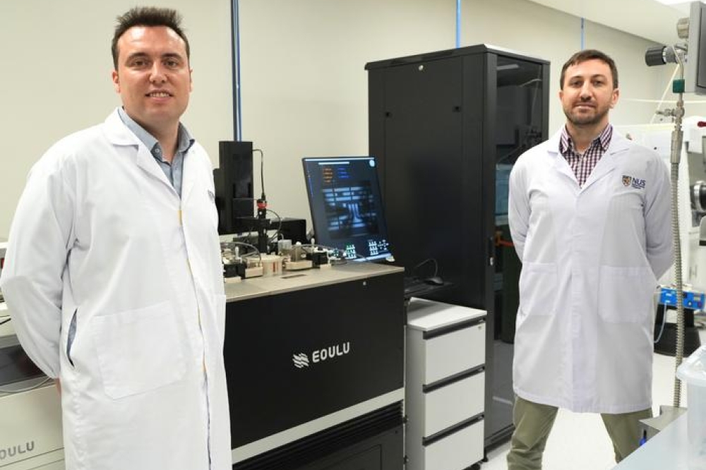
BY RUI SHAO, JISHEN ZHANG AND XIAO GONG FROM THE NATIONAL UNIVERSITY OF SINGAPORE
There are a number of exciting applications involving the use of photonics in the short-wave infrared, which is a spectral domain spanning 900 nm to 2.5 µm. This region is employed for advanced driver assistance systems, biomedical imaging and high-speed optical interconnects.
Regarding the latter, demand is on the rise, spurred on by surging interest in artificial intelligence. In this revolutionary form of computing, there are compelling arguments for transmitting and receiving data via infra-red light through optical fibres, rather than routing electrical signal through copper wires.
However, to ensure that this shift in transceiver technology is successful, optical receivers must combine a high bandwidth with a superior signal-to-noise ratio and a high detection efficiency – and ideally, accomplish all of this using monolithic electronic-photonic integration.

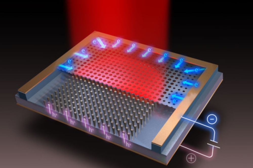
Figure 1. Three-dimensional illustration of the InGaAs APD with
photon-trapping structures and the unit cell of the device with detailed
layer structures.
Against this backdrop InGaAs-based avalanche photodiodes (APDs) are gaining a great deal of attention, thanks to their exceptional sensitivity, compact footprint, and broad absorption spectrum. With this class of detector, there has been significant progress in responsivity and bandwidth, for devices on both InP and silicon substrates.
For those that produce APDs, if there’s a need to increase responsivity, the well-trodden path is a thickening of the InGaAs absorption layer. However, there’s a penalty to pay for this – an increase in carrier transit time that applies the brakes to the detector’s speed. And that’s not the only downside, as a thicker absorber also exacerbates dark current, degrading the signal-to-noise ratio.
A variety of reflector-based techniques have been explored to address these challenges. But there’s also a more efficient alternative, involving the integration of a photon-trapping structure within the APD. With this approach, there’s enhanced light absorption, realised without the need for complex reflector designs or additional epitaxial growth. Instead, engineers draw on the synergy between thinner active layers and photon-trapping microstructures to boost bandwidth and photon efficiency simultaneously.

Figure 2. Cross-sectional scanning electron microscopy images of the
photon-trapping APD on the silicon-on-insulator substrate. (a)
Cross-sectional view of the active mesa region with the photonic crystal
array. (b) The zoom-in view of the photonic crystal with III-V
epilayers. (c) The zoom-in view of the interface at the SU-8 bonding
layer and III-V epilayers.
Inspiration for photon trapping is found in nature. There are natural light-trapping mechanisms in biological structures, such as butterfly wings and moth eyes, that maximise absorption through micro- and nano-scale arrangements, effectively guiding incident light into the lateral plane rather than reflecting it away. Device designers adopting these strategies can realise highly efficient light absorption in a thin InGaAs layer, and significantly enhance detection efficiency without sacrificing bandwidth.
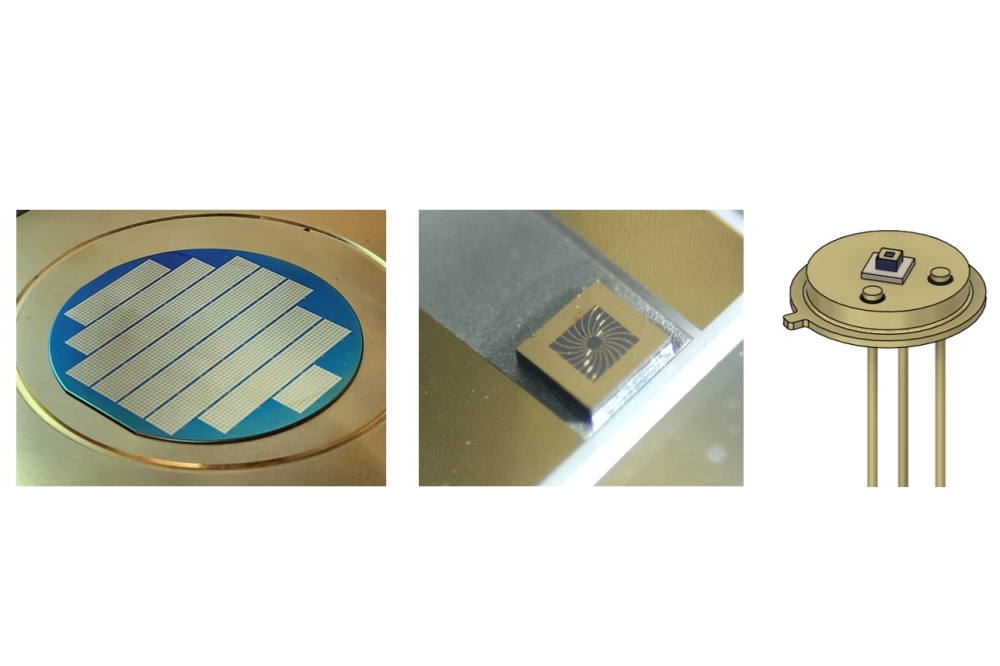
Despite the tremendous promise that photon-trapping has in helping to produce high-performance InGaAs APDs, research in this area is limited. But we are addressing this at the National University of Singapore by pioneering the development of InGaAs/InAlAs APDs that incorporate photon-trapping structures. We have successfully integrated these detectors onto a silicon-on-insulator substrate.
Strengths of our APDs include a responsivity of 0.75 A W-1 at unity gain, realised with an InGaAs absorption layer around just 250 nm-thick. Additionally, we have achieved a remarkable enhancement in external quantum efficiency compared with conventional InGaAs APDs, for a spectral range spanning 1550 nm to 1630 nm.

Figure 3. Current-voltage (I-V) characteristics of the APDs (a) without
photon-trapping structures at 1550 nm, and (b), with photonic-trapping
structures at 1626 nm, by varying the intensity of illuminated light.
(c) The plot of photocurrent versus light intensity at unit gain. (d)
Multiplication gain of the APDs with and without photon-trapping
structures at different voltages.
Comprehensive simulations guided our device design and fabrication process. Using this approach, we have produced APDs with a dark current of just 51.3 nA at 90 percent of the device’s breakdown voltage, and a maximum multiplication gain exceeding 100. The high-performance of our devices is also highlighted by detectivities of 9.34 x 10¹⁰ Jones at 4 V and 3.43 x 10¹² Jones at 24.1 V, along with a broad operational voltage range, spanning 4 V to 24.1 V.
Light-trapping mechanisms
For normal incident light, which primarily propagates vertically, absorption scales with InGaAs layer thickness. However, there’s more to consider when evaluating our devices. Note that conventional vertical resonance modes yield narrow spectral responses and negligible lateral light confinement – and with our photon-trapping structure, incident photons are instead coupled into lateral propagation modes, trapping light within the plane via the surrounding InAlAs layer and the SU-8 cladding.
At the core of our innovative design are two-dimensional photonic crystals, formed from etching nanostructures into the device surface. With these novel APDs, incoming light is diffracted and reflected at the two-dimensional photonic crystals, to create coupling into lateral propagation modes that confine photons within the InGaAs absorber (see Figure 1 for the unit cell structure and key design parameters of our device, which incorporates a separate-absorption-grading-charge-multiplication region that features a multiplication layer and an InGaAs absorption layer, approximately 200 nm and 250 nm thick, respectively).
To quantify the impact of our two-dimensional photonic crystals, we conducted electrical and optical simulations. They reveal that introducing these photonic structures generates localised electric field peaks at the edges, while simultaneously reducing the electric field in the upper multiplication and absorption regions. Based on these findings, we are aware that there is a need for careful design of geometrical parameters, to avoid premature breakdown and a field-related tunnelling current.

Figure 4. Extracted responsivity and external quantum efficiency (EQE) versus wavelength.
Additional optical simulations by our team explored the impact of variations in the period, radius, etch depth, and lateral etching distance of our two-dimensional photonic crystals, as well as the SU-8 bonding-layer thickness. This effort enabled us to carefully select the geometry for our APDs, by considering both the results of our simulations and practical constraints. The designs that followed provide diffraction-enabled light confinement, and lead to the formation of multiple resonance peaks within the InGaAs absorption layer, further amplifying absorption efficiency.
Guided by our simulations, we fabricated devices using an optimised process. We began by loading an InP substrate into an MBE chamber and depositing a stack of III-V epilayers. To form two-dimensional photonic crystals, we patterned our epiwafers using electron-beam lithography, prior to inductively coupled plasma reactive ion etching to create structures with a desired depth and slanted sidewalls. After that, we formed a tungsten electrode by sputtering and lithography.
The next steps began by spin-coating an SU-8 adhesion layer on the SOI substrate. We then bonded III-V die in a flip-chip manner, applying a pressure of 80 N cm-2 at 150 °C for 30 minutes. To ensure light trapping in the InGaAs absorber, we carefully optimised the thickness of the SU-8 bonding layer to be consistent with optical simulations.
From an industrial perspective, there is a preference for oxygen plasma-assisted oxide bonding. By adopting this approach that’s been extensively studied and widely adopted for III-V-to-silicon wafer-to-wafer bonding, we have been able to efficiently fill our etched two-dimensional photonic crystals on the InP substrate with an oxide cladding, prior to chemical mechanical polishing.

Figure 5. (a) Reverse dark current density versus the reciprocal of mesa
radius at 90 percent breakdown voltage. (b) Dark current versus the
number of photonic crystals at 90 percent and 95 percent breakdown
voltage.
Heterogeneous integration followed, by bonding a III-V wafer to silicon wafer. Note that this procedure for filling two-dimensional photonic crystals is fully compatible with existing III-V-to-silicon wafer-to-wafer bonding technology.
Fabrication of our devices is completed by: removing the InP handle substrate with concentrated HCl, a step that involved partial etching of the InGaAs etch-stop layer to reduce undesired absorption during measurements; deposition of a contact metal; mesa etching, using H3PO4/H2O2/H2O solution to minimise surface defects; and passivating the device, using a SU-8 cladding layer.
We have inspected our APD with a scanning electron microscope, which is helpful when characterising the photonic crystal array (see Figure 2 (a)). This form of microscopy clearly reveals truncated-cone-shaped two-dimensional photonic crystals with smooth slanted sidewalls. Zooming in, smooth and flat interfaces are visible between the III-V active layers and the SU8 adhesion layer on the SOI substrate (see Figure 2 (b)). Clear layer structures for the III-V stack (see Figure 2 (c)) confirm that MBE growth realises well-controlled layer thickness and elemental compositions.

Figure 6. Arrhenius plot of the control and photonic-trapping APD at (a) 10 V, and (b) 20 V, with extracted activation energies.
Device evaluation
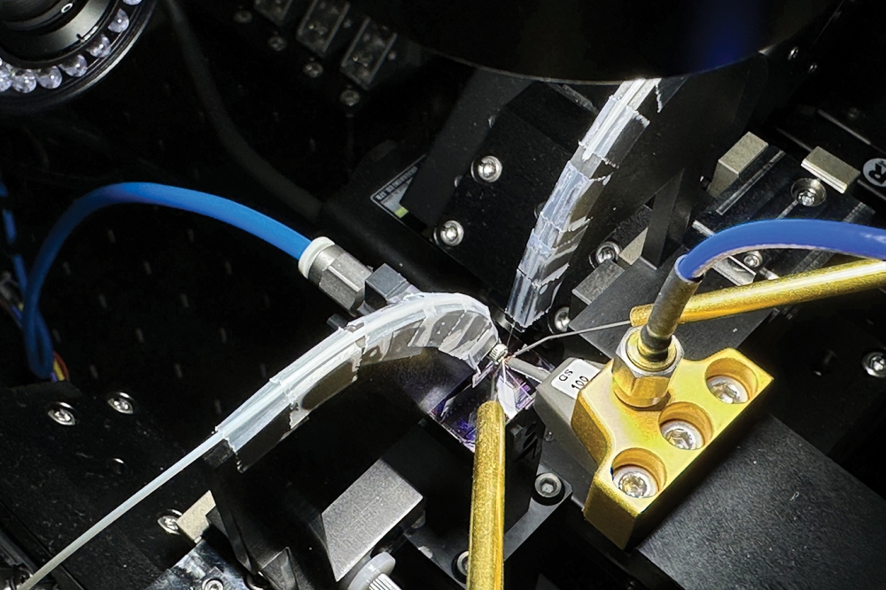
Electro-optical characterisation began by plotting current-voltage curves for our control APD and the photon-trapping APD, with a mesa radius of 15 mm, both with and without light illumination (see Figure 3 (a) and (b)). For measurements under illumination, we employed a lensed fibre to direct light with an intensity ranging from -49.9 dBm to -19.9 dBm on the active region.
This investigation uncovered a significantly reduced punch-through voltage for the photon-trapping APD, attributed to local electric-field peaks at the edges of the two-dimensional photonic crystal in the InGaAs absorber. This partially high electric field drives photogenerated carriers in the InGaAs layer into the InAlAs multiplication layer.
Measurements conducted at 90 percent of the breakdown voltage recorded dark currents for the control APD and the photon-trapping APD of 16.9 nA and 51.3 nA, respectively. While the dark current of the photon-trapping variant is higher, it is still acceptable, thanks to proper engineering of the two-dimensional photonic crystal shapes that ensures effective minimisation of the field-related tunnelling dark current. Also helping to improve performance are the slanted sidewalls that efficiently smooth the electric-field and prevent premature breakdown.
Via variations in input power, we have measured and extracted optical response current characteristics (see Figure 3 (c) for the extracted steady-state photoresponsivity of the control APD and the photon-trapping APD at a unit gain). Both devices realise a multiplication gain of more than 100 (see Figure 3 (d)). The photon-trapping APD realises responsivities of 0.75 A W-1 at 1626 nm and 0.39 A W-1 at 1550 nm, resulting in external quantum efficiencies of 57.2 percent and 31.2 percent, respectively. Compared with the control, the photon-trapping APD offers enhancements by factors of 2.38 and 1.3 at 1626 nm and 1550 nm, respectively.
We have looked in more detail at the absorption spectra of both types of APD, considering unit gain. This involved extracting wavelength-dependent responsivity, by varying the light intensity and wavelength of a narrow-linewidth tuneable laser. For the photon-trapping APD, we recorded a broadband enhancement of light absorption from 1536 nm to 1630 nm, and a maximum peak of 0.75 A W-1 at 1626 nm (see Figure 4). These results showcase the effectiveness of the photon-trapping mechanism, which offers tunability of the absorption peak through changes in the periods and radii of the two-dimensional photonic crystals.
As well as enhancing optical performance, photon-trapping significantly impacts the electrical field inside the device. To understand the leakage mechanism in our photon-trapping APDs, we extracted dark current density, plotting values for different mesa radii under voltages equal to 90 percent and 95 percent of the breakdown voltage (see Figure 5 (a) and (b)). This investigation uncovered a strong dependence of the dark current on the two-dimensional photonic crystal’s area, and indicated that the perimeter leakage current is the dominant leakage source at high reverse biases.

Table 1. Benchmark of the APDs for SWIR detection, including InGaAs, InP, germanium, and GaSb material systems.
To understand the leakage generation mechanism, we recorded the temperature-dependence of the reverse dark current between 240 K to 320 K (see Figure 6 for Arrhenius plots of the dark current for both devices). This study found that at small reverse biases, the dark current of both forms of APD increases slightly with increases in temperature. We account for this by considering more severe thermal generation. At a bias of 10 V, both forms of APD have comparable activation energies, while a slightly smaller activation energy is obtained in the photon-trapping APD at a larger reverse bias of 20 V. These observations suggests that the tunnelling-related generation of the dark current is more prevalent in photon-trapping APDs at larger reverse biases.
One of the downsides of dry etching the III-V epilayers in the active region is that it creates a long-term degradation issue. There’s an increase in dark current, predominantly generated in the upper side of the absorbing layer that’s close to the InAlAs multiplication layer. Another impediment to a low dark current, as well as the reliability of the photon-trapping APD, is ion implantation into the charging layer. For our devices, the etch depth for the photon-trapping APDs is only around 220 nm, so 130 nm away from the top surface of the InGaAs absorber. By tuning the period and radius of the photonic crystal, we will be able to further reduce the etch depth and enhance long-term reliability.
Additional weaknesses associated with dry etching III-Vs include surface roughness and damage, which leads to surface traps and defects at the sidewalls. We have adopted a few approaches to reduce surface damage. Our efforts include using low-ion-energy dry etching, followed by a few seconds of wet etching, to reduce surface damage caused by ion bombardment. Filling the III-V voids with SU-8 helps to passivate dangling bonds.
We have benchmarked our photon-trapping APDs against surface-illuminated germanium-on-silicon APDs, InGaAs-based APDs on various substrates, and AlInAsSb APDs with photon-trapping structures (see Table 1). This comparison, using key figures-of-merit, demonstrates that our devices exhibit outstanding performance in terms of responsivity, multiplication gain, and dark current, even with thin InGaAs/InAlAs layers on the SOI substrate. This underscores the great potential for improving optical performance with photon-trapping structures, and especially heterogeneous integration with silicon photonics.
Our work is a significant milestone in developing III-V APDs for future optoelectronic integrated circuits. Strengths of our success include: a 2.38 times enhancement in external quantum efficiency; the heterogenous integration of high-performance InGaAs/InAlAs APDs on the silicon photonics platform, using a large-scale manufacturable integration approach; and a comprehensive analysis and characterisation in
the optical and electrical domains, providing an in-depth understanding of photon-trapping structures. This work lays the foundation for photon-trapping APDs to serve in driver assistance systems, biomedical applications and next-generation computing.