Technical Insight
GaN HEMTs: faster, more capable and better understood
Low-resistance channel contacts that speed transistors to record-breaking frequencies, localized boron doping that boosts blocking voltages and studies of HEMT ageing mechanisms all featured at the latest International Electron Devices Meeting. Richard Stevenson reports.
Advances in silicon technology have dominated the agenda at the International Electronic Devices Meeting (IEDM) for more than fifty years. However, recently this meeting has also featured a handful of presentations on GaN HEMTs, showcasing the progress made with this device. According to papers at the most recent meeting, not only is this class of transistor operating at far faster speeds than ever before and blocking higher voltages – a more detailed understanding of why it fails is coming to light, and superior models are being developed to aid the building of circuits based on these HEMTs.
One of the highlights from the latest IEDM, which was held in San Francisco from 6-8 December 2010, was a paper from a team from HRL Laboratories claiming the record for the fastest GaN HEMTs. These transistors, which have gate lengths as short as 40 nm, produce a peak cut-off frequency of 220 GHz and a maximum oscillation frequency of 400 GHz. The record-breaking results are believed to stem from an impressive set of DC characteristics: on-resistance is just 0.81 Ω.mm; drain current hits 1.61 A/mm; off-state breakdown voltage is 42 V; and extrinsic transconductance peaks at 723 mS/mm, reducing the contribution from parasitic capacitances.
HRL’s HEMTs employ a barrier made from AlN. This wide bandgap material has the benefit of producing strong polarization effects, but it also creates a high potential barrier for electrons, making it difficult to form a lowresistance ohmic contact to the channel. The issue is addressed by re-growth of heavily doped GaN contacts by MBE, according to West-coast team. They have fabricated double heterostructure HEMT epistructures by MBE on 3-inch SiC. An Al0.08Ga0.92N layer was deposited first, followed by a 20 nm-thick GaN channel and then a top barrier comprising 3.5 nm of AlN and 2.5 nm of GaN (see Figure 1). The thin top barrier cuts gate-to-channeldistance while maintaining a high two dimensional electron gas density and a low gate-leakage current.

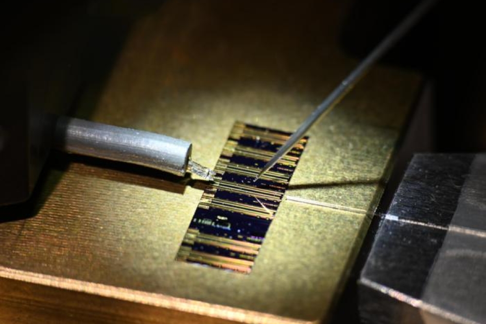
Figure 1. MBE re-growth of heavily n-doped GaN contacts has helped to speed HRL’s HEMTs
The HRL team produced transistors with gate lengths ranging from 40 nm to 200 nm. Chlorine-based reactive ion etching exposed part of the channel, before MBE added 50 nm-thick GaN layers with a silicon doping level of 7 x 1019 cm-3. These formed the basis for source and drain electrodes that were created by adding titanium and platinum. A tri-layer electron-beam technique created T-shaped gates made from platinum and gold, before these devices were passivated with 50 nm of SiN.
Cutting gate length from 200 nm to 40 nm increased transconductance from 672 mS/mm to 723 mS/mm and reduced threshold voltage by 0.5 V, indicating that gate scaling was not impeded by short channel effects. Measurements of the cut-off frequency at a range of gate lengths confirmed this and indicated that miniaturization reduced parasitic delay. Modeling showed parasitic charging time accounted for one-tenth of the total delay time for 40 nm transistors with a source-drain voltage of 2 V. The gate transit time scales with gate length, which is another promising sign that further reductions in device size should increase the speed of these transistors.
Channel stoppers
Modifications to transistor architectures were also behind the hike in blocking voltages of HEMTs produced by Panasonic’s Advanced Technology Research Laboratories. By introducing an array of ‘channel stoppers’ that terminate the leakage current at the interface with the silicon substrate, this team increased off-state breakdown voltage in HEMTs with GaN layers just 1.4 μm thick from 760 V to 1340 V. Turning to 1.9 μm-thick GaN bolstered the blocking voltage to 1900 V, and the team claims that additional thickening of GaN should increases this to 3 kV.
Simply increases the thickness of GaN layers in conventional devices – which could find application in power switching systems, such as inverters for industrial use and uninterruptible power supplies – has been widely touted as a route to increasing the HEMT’s blocking voltage. But in practice such efforts, which have the downside of increasing chipmaking costs, fail to deliver on this front. The reason for this was unclear until the recent efforts by this Japanese team. According to them, conventional devices suffer from a significant leakage current that stems from sheet electrons forming an inversion layer at the substrate-epilayer interface. The Kyoto team has confirmed the presence of an inversion layer by fabricating metal-insulator-semiconductor diodes and measured their capacitance-voltage characteristics.
To stem the flow of leakage current, Panasonic’s engineers insert channel stoppers. These stoppers, which are formed by selective boron ion implantation at the periphery of the chip, widen the depletion layer in silicon at high positive surface bias. This, in turn, increases the overall blocking voltage thanks to the addition of the breakdown voltage of the depletion layer.

Figure 2. Introducing boron-doped channel stoppers delivers a hike in the HEMT blocking voltage
Unreliable reliability tests
Meanwhile, researchers Jungwoo Joh and Jesús delAlamo from MIT have revealed that it can be inappropriateto determine a HEMT’s RF reliability from DC tests. That’sbecause the degradation mechanisms for DC and RFoperation are significantly different.
“Obviously life tests under RF conditions close to field, but mildly accelerated, would best represent the reliability of these devices,” said Joh to Compound Semiconductor. He and del Alamo found that RF stress degrades a device far more severely than DC stress at the same voltage, and this degradation gets more severe with increasing power compression. In addition, the pair of MIT researchers discovered that RF stress induces an increase in source resistance due to a new mechanism that is possibly related to hot carriers. The key message of their study is this: DC life tests underestimate RF reliability.
This important conclusion was drawn from a series of measurements on single-stage MMICs with 4 x 100 μm GaN HEMTs. Performance was evaluated at a current of 100 mA/mm, a source-drain voltage of 28 V, and a saturated power output (input power was 23 dB). The RF performance at this voltage is similar to that at 40 V, the designed operating condition for these MMICs.
The first experiment began by DC stressing the device for 5 hours, using a drain-source voltage of 40 V and a quiescent current of 100 mA/mm. This led to little change in device characteristics, aside from a small increase in current collapse. An RF stress test followed, involving increases in input power from 20 dB to 26 dB. This led to major changes in MMIC performance: significant increases in current collapse and sheet resistance; a permanent degradation in the maximum drain current; and a substantial cut in the output power.
Joh and del Alamo then looked in turn at three operating conditions that could potentially cause enhanced degradation at high compression: the “on” regime, the high-voltage “off” regime; or the “high-power” regime. They ruled out the first two, and although they couldn’t directly test the third scenario – in this condition there is very high power dissipation, which leads to incredibly high channel temperatures that kill the device – pulsed conditions revealed a sharp increase in sheet resistance beyond 40 V, especially for a high stress current.
Fluorine: a fine dopant
Reliability assessment was also the central theme of astudy led by Kevin Chen from Hong Kong University ofScience and Technology. He and his colleagues studiedthe behavior of enhancement-mode AlGaN/GaN HEMTsfabricated by fluorine plasma ion implantation. Thistechnique offers a low-cost approach to making this class of transistor and has the merit of self-alignment betweenimplantation and gate metallization.
In GaN and related materials, fluorine ions exhibit a negative charge state. “When incorporated in the AlGaN barrier, these ions can deplete the two-dimensional electron gas channel, shifting the threshold voltage to positive values and converting the device from depletionmode to enhancement-mode,” explains Chen. The enhancement-mode form of the device, which is also referred to as ‘normally off’, is more desirable for power switching applications - it allows a simpler gate drive; and if it fails, the system is left in a safe state.
Fluorine plasma ion implantation technology has been previously used in other semiconductor materials, such as silicon and GaAs, where it has compromised reliability. The concern has been that this technology would also impair GaN transistor reliability, although preliminary results indicate that this does not impact the electrical and thermal reliability of device made from this wide bandgap semiconductor.
The team, led by Chen and including John Roberts from the US GaN-on-silicon HEMT trailblazer Nitronex, has recently focused their efforts on studying reliability under high gate bias and low drain bias, the standard condition for operating a power switch in its “on” state. In this state, especially when the gate is overdriven to either minimize the on-resistance or accommodate current surge, the Schottky gate tends to feature a non-negligible current –this also raises reliability concerns.
One of the goals of the team’s recent work has been to investigate whether the fluorine ions, which are mostly located in the gate barrier layer, are stable under gate forward overdrive. If they are unstable and cause reliability issues, the team would aim to identify the critical gate bias and consequently the operating conditions to drive a device without degradation.
The team fabricated AlGaN/GaN HEMTs with a 1.5 μm gate length and gate-source spacing, and a gate-drain spacing of 2 μm. They found that the critical gate overdrive voltage was 3.6 V and 2.8 V at drain-source voltages of 2 V and 0.85 V, respectively. At higher voltages, the channel turn-on voltage experienced a small, persistent negative shift, and at lower voltages the transistor realized excellent stability.
The negative shift in channel turn-on voltage is an undesirable characteristic. “A large negative shift means that the E-mode device could eventually drift to a D-mode one,” explains Chen. “In practice, we need to stabilize the on-voltage at the positive value.”
Impact ionization of fluorine ions due to hot electron injection is viewed as the primary driver behind the shift in on-voltage with temperature. “Impact ionization is one of the few reliability-relevant physical processes that becomes weaker as temperature goes up, “ says Chen. “In semiconductor devices, most degradation processes could be accelerated at higher temperature. With regard to the on-voltage shift, it becomes smaller and eventually disappears as the temperature is raised.”
Modeling HEMTs
The various approaches to modeling the behavior of GaNHEMTs in RF power amplifiers was touched on in a paperby David John and co-workers at NXP Semiconductors,who have pioneered the development of a surfacepotentialbased model. This joins a growing list of modelsfor predicting HEMT behavior, which all have theirweaknesses, according to John. Table-based models,which use an interpolating spline on measured data, cangive erroneous values for bias outside the range.Threshold voltage based models can struggle at thresholdvalues and empirical models fail to scale. We cannotpredict how geometrical changes impact performance.
“From metal-oxide-semiconductor modeling, surfacepotential- based models are known to be the preferred approach for scaling, extrapolation, distortion modeling, statistical modeling and so on,” says John. “ All Compact Model Council standardization efforts focus on the surface-potential-based models for this reason.”
NXP’s model resembles that for a conventional MOSFET. However, it reflects one fundamental difference between these two types of transistor: HEMTs are based on accumulation at the surface, while MOSFETs operates in inversion. To account for this, John and his co-workers derived the equations for currents and charges from scratch using nonlinear, binomial expansions of the electronic charge density. After the engineers had constructed this core model that provides fast simulation times, they compared its predictions to numerical simulations of a gated section of a full device.
“The numerical simulations checked that the approximations we have made in order to arrive at compact expressions are consistent with the idealized structure that we are using to describe the device,” explains John. These efforts showed that the core model is good at describing current as a function of bias and catering for the bias dependence of the capacitance.
The researchers then built a macromodel that encompasses the core model. This is claimed to account for the regions under the gate foot and the drain-side gate edge with an approach that is based on physically justifiable differences in the underlying model parameters. Resistors, capacitors and inductors describe passive parasitic elements and the rise in device temperature resulting from power consumption is captured with a simple thermal network.
To test the model’s validity, NXP researchers have compared its predictions to real data obtained from onwafer measurements of multiple-finger, multiple-cell GaN HEMTs. This effort revealed that the model captures DC measurements at different temperatures, including a negative output conductance at high powers that stems from strong self-heating.
Simulations of RF behavior are also close to measured results, according to capacitance and transconductance comparisons at 2.6 GHz.
The model can also be used to simulate circuits after it has been calibrated to measurements, a necessary step for any compact model. “We are constantly working to improve our model, and to further validate and benchmark it,” says John. “There is still work to do.”
That view holds true for many other aspects related to the GaN HEMTs. The good news, however, is that progress is clearly being made on many of these fronts. It will be interesting to see what IEDM hold in store at the end of 2011.
© 2011 Angel Business Communications. Permission required.