Technical Insight
CS Mantech shines a spotlight on GaN

Existing and emerging opportunities for GaN transistors and ways to make them even better lay at the heart of this year's CS Mantech.
By Richard Stevenson
Shortly after the turn of the millennium, GaAs Mantech became CS Mantech. And hindsight shows that those behind the decision to rename the conference made a wise decision. While developments in GaAs devices and manufacturing technologies still feature heavily at this gathering, many of the talks are now devoted to advances in GaN.
That was certainly the case at this year's meeting, held from 18-21 May in Scottsdale, Arizona. At this conference some speakers showcased the tremendous performance that products made from GaN can offer, while others either highlighted new markets where this class of device can serve, or unveiled new approaches for either addressing weaknesses in reliability or taking breakdown voltages to new highs.
One area where GaN can make an impact is in mobile devices. These gadgets have transformed our lives, providing access to e-mail and the web when on the move − but by the end the day, we are often hunting around the house for a cable, so that we can re-charge the battery. A move to a wireless power supply for charging the mobile would be very welcome, and approaches involving GaN transistors are showing much promise, according to a paper delivered by Tatsuya Hosotani from Murata Manufacturing Company.
Hosotani and his co-workers started considering the use of GaN transistors for wireless power supply and wireless charging in 2009, and in Scottsdale he announced the results of experiments that showed a power conversion efficiency from the DC power source to the load, via RF transmission, of 89.5 percent (see Figure 1). The output power of this wireless power supply was 22.4 W.
The frequency selected for power is regulated, in order to minimise interference with mobile devices. There are industrial, scientific and medical (ISM) radio bands that have been allocated for these uses, rather than that of communication, and they exist at 6.78 MHz and 13.56 MHz. The Murata team have used the lower of these bands, building wireless power supplies with GaN FETs from EPC.
Figure 1 : For wireless power supplies, GaN FETs are more efficient than those made from silicon, and they are capable of transmitting more power. The y-axis is percent efficiency.
Inducing electromagnetic resonance transfers power. DC power is intermittently supplied to create a RF electromagnetic resonance field, which is transmitted and then converted back to a DC form. Note that this technology is not restricted to supplying power to mobiles and tablets, and could be used for small battery-powered electronic devices and communication cards.
Measurements of power conversion efficiency were made with a system featuring a single loop of copper wire with a diameter of 2 mm and a radius of 50 mm. With coils separated by 3 mm, an output voltage of 61.8 V and a supplied power of 22.4 W were realised at an input voltage of 18 V. In comparison, a system with silicon FETs produced an inferior efficiency of 87.1 percent, and due to the poor performance of this class of transistor at high frequencies, power supplied by this system was restricted to below 10 W.
"We will be able to get to even higher efficiencies by devising a new power conversion technique and by using new power compound semiconductor devices," explained Hosotani in an interview with Compound Semiconductor. He expects the first commercial wireless chargers incorporating GaN FETs to hit the market two or three years from now. To enable this, he and his co-workers will be developing power transmitting and receiving modules for various products.
Measurements determined that GaN FETs could form a wireless power supply with a DC-RF-DC power efficiency of 89.5 percent. Operating at 6.78 MHz, this system produced an output power of 22.4 W.
To higher voltages
One of the weaknesses of the GaN-on-silicon HEMT is its relatively low breakdown voltage. To increase this, a team from the Institute of Electronics, Microelectronics and Nanotechnology in Villeneuve d'Ascq has developed a new device architecture that involves local substrate removal (see Figure 2). This modification to the design supresses parasitic substrate conduction, and holds the key to propelling blocking voltages to 2.3 kV.
"This is a record breakdown voltage," claimed the leader of this team, Farid Medjdoub, who pointed out that this record was realised with a barrier thickness below 10 nm. And even higher voltages are possible, with the team to soon publish a paper reporting a 3 kV AlGaN/GaN transistor.
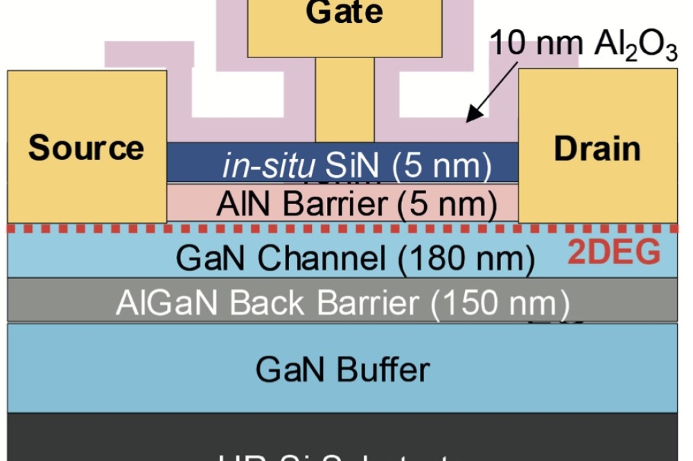
The work described at CS Mantech involves 4-inch GaN-on-silicon epiwafers grown by EpiGaN. They feature a 5.5 µm-thick buffer, a GaN channel with an unspecified thickness, a 6 nm-thick AlN barrier, and a 3 nm-thick Si3N4 cap layer.
Device formation began with the addition of an ohmic contact formed from a
Ti/Al/Ni/Au metal stack. This step involved removal of part of the SiN film. Following rapid thermal annealing of these contacts at 875 °C, devices were isolated by nitrogen implantation, before gates with a length of 1.5 µm were defined by electron-beam lithography. The gate metals, a pairing of nickel and gold, were deposited on top of the AlN layer by carefully etching the SiN cap with a low-power SF6 plasma.
Thinning and polishing of the substrate to 200 µm followed, before wafers were loaded into an STS tool, where reactive ion etching removed silicon up to the buffer layer in the area around the drain of the transistor.
"It takes about 90 minutes to locally etch the 200 µm-thick silicon substrate," explained Medjdoub, who believes that the process is fully compatible with high-volume production, because backside-silicon deep etching is commonly used in industry.
Figure 2: Partial removal of the silicon substrate can propel blocking voltages for the GaN HEMT to 2.3 kV.
The team compared the DC characteristics before and after substrate removal, considering 50 µm-wide devices with a 30 mm gate-drain spacing. At a gate-source voltage of 2 V, the DC output current density dropped from 0.55 A/mm to 0.45 A/mm after etching, due to degraded thermal dissipation within the trench. This also impacted the specific on-resistance, which climbed from 4.1 mΩcm2 to 4.6 mΩcm2 following local substrate removal.
Superior breakdown voltages stemming from substrate removal only occur at longer gate-drain distances (see Figure 3). When these contacts were 30 µm apart, the conventional device blocking voltage was around 1.6 kV, compared to 2.3 kV for a comparable device featuring substrate etching.
Adding field plates and dielectrics under the gate promises to take the performance of these devices to a new level. "This is definitely in our plan," said Medjdoub, who is aiming to include these refinements in a normally off transistor.
Cutting current collapse
One of the biggest weaknesses of the GaN HEMT is that it can suffer from current collapse: That is an increase in the on-resistance after the transistor is switched from the on to the off state.
This is believed to originate from a trapping of electrons on the AlGaN surface.
Figure 3: Benefits of higher blocking voltages are uncovered at greater gate-drain distances.
Several ways have been proposed to address current collapse, including high-pressure, water-vapour annealing, which is an approach developed by a team from the University of Fukui and Nara Institute of Science and Technology, Japan. At this stage of research, the spokesman for this team, Joel Asubar, told Compound Semiconductor that they cannot be certain that their approach is the most successful one for addressing current collapse − but they are convinced that it is one of the simplest methods for doing so.
Evaluation of the high-pressure, water-vapour annealing process involved treating devices prior to SiN passivation (see Figure 4). GaN-on-SiC HEMTs featuring a 25 nm thick Al0.2Ga0.8N barrier were subjected to annealing at 0.5 MPa for 30 minutes at temperatures of 200 °C, 300 °C and 400 °C.
Measurements revealed that the maximum current density for the device was nominally identical to that of a control sample, indicating that high-pressure water vapour-annealing did not induce any significant change in the DC operation of the device.
To represent current collapse quantitatively, the team evaluated the normalised dynamic ratio of the device. They defined this figure-of-merit as the ratio of the dynamic on-resistance to the static on-resistance. It tends to one when the device is subjected to longer pulses, which will allow more time for the detrapping of electrons "“ and greater recovery of the dynamic on-resistance (see Figure 5).
Figure 4: High pressure annealing in water vapour is able to cut current collapse in GaN HEMTs
This result indicates the capability of addressing current collapse with high-pressure water vapour annealing, which is argued to be a process that is compatible with high-volume manufacturing. "All we need is a heater, high-purity deionized water and a chamber. These are all readily available in any semiconductor fabrication facility," said Asubar.
With work still at an early stage, the impact of the annealing process on HEMT performance is still under evaluation. "But at this point, we have not obtained any data suggesting high-pressure water vapour annealing degrades HEMT performance," claimed Asubar.
He and his co-workers are trying to understand why the annealing process cuts current collapse. Simulations that fit curves to data for the normalised dynamic ratio as a function of pulse length suggest that HEMTs have six trap levels with energies between 0.28 eV and 0.6 eV. However, this reduces to two traps at 0.28 eV and 0.37 eV after annealing. Meanwhile, X-ray photoelectron spectroscopy suggests that annealing leads to formation of an oxide layer, which is suitable for passivation and the filling up of near-surface nitrogen vacancies.
Figure 5: A high-pressure water-vapour anneal (HPWVA) reduces the normalised dynamic resistance, which is the ratio of dynamic on-resistance to static on-resistance. tON is the length of the applied pulses.
One of the next goals for the team is to determine if their annealing process impacts the long-term performance of devices. "Also, aiming for collapse-free operation, we have done preliminary work on combining high-pressure water-vapour annealing with field-plate approaches," revealed Asubar. "Our initial results are promising."
Perfecting the package
The higher powers produced by RF GaN devices have fuelled efforts to develop new packaging technologies that offer a low-cost, effective approach to thermal management. The traditional approach for housing of high-power RF components is to use metal-ceramic packages and assembly processes (see Figure 6). Products that result are reliable, consistent, and capable of dissipating heat, but production costs are very high and throughput limited.
Figure 6: Co-planar (left) packages tend to feature plastic overmoulded parts that trim cost, but impair heat extraction when they are used in PCB circuits. Multi-level packages made from metals and ceramics address this, because the bottom of the package can be in contact with the carrier. However, this approach is expensive. Multi-level plastic overmould parts made by MACOM offer the best of both worlds, combining low cost with good thermal management.
"For a traditional multi-level package there is usually more cost in the package materials and assembly than the die, even for GaN. The range is from about 40 percent to 75 percent," explained Quinn Martin from MACOM Technology Solutions.
For this reason, there are times when die are packaged in a co-planar technology, which has the the source and pins at the same level "“ usually on the backside of the package. With that design, the part can be surface mounted onto a printed circuit board along with all the other components through a reflow process.
Plastic overmould parts are manufactured in this way, and they lead to significant cost savings compared to a metal-ceramic multi-level package. According to Quinn, the cost reduction is not just a few percent, but is measured in factors such as 1X, 2X, etc.
However, the downside of this approach is that for heat to get out of the device, it must first travel through the package and PCB before it reaches a better heatsink, the metal carrier (see Figure 7). The PCB is a terrible material for heat dissipation, with a thermal conductivity below 1 W/m-K, and this governs the poor thermal dissipation of the die.
Multi-level packages address this issue. The source and the pins are at different heights, so the electrical connections can be made through the leads at the top of the PCB, while the source rests on the heat sink near the bottom of the PCB. But the downside is the cost, due to the use of metal-ceramic air cavity packages.
Figure 7. Heat extraction with co-planar parts is poor, due to the very low thermal conductivity of the PCB material (top). Turning to a multi-level part improves heat extraction (middle), and this can be aided by switching from a eutectic to an epoxy that features metal particles (bottom).
To drive down costs, MACOM has produced a package that offers the best of both worlds: It has the thermal benefits of a multi-level package, while adopting the plastic overmould assembly process.
"We have released products with this technology and are running regular volumes in production," explained Martin. These products can deliver a CW output of up to 200 W, while still operating below the maximum junction temperature for the device.
Development of this alternative packaging technology has involved selecting and qualifying mould compounds for the different package types and device technology. Traditional mould compounds for plastic parts have a glass transition temperature of 115 °C to 140 °C, and above that they transition from a hard to a rubbery state, which has a different thermal expansion coefficient, and can damage the device and the wire bonds. However, turning to new overmould materials can address this, because they have glass transition temperatures of 170 °C to 235 °C.
Figure 8: Loadpull measurements at 30 GHz on a pre-matched 8 x 50 μm device biased a 20 V.
MACOM has also made advances in the material used to attach the die to the package. In air cavity packages, AuSi and AuSn eutectics are often used to bond the die to a metal flange. This provides a reliable, low-thermal-resistance connection. But for plastic packages, thermal conductivity is compromised by epoxy die, which is used because it is more compatible with the associated production equipment.
Improvements are possible by turning to new materials that incorporate gold, silver or copper particles in an epoxy/organic matrix. When properly cured, sintering results in a material capable of combining a strong bond with a thermal conductivity that can be higher than that of a eutectic and hit 200 W/m-K.
High-frequency GaN
One company with a strong pedigree in high-frequency GaN amplifiers is Qorvo, a firm formed in early 2015 from the merger of TriQuint and RFMD. At this year's CS Mantech, it took the opportunity to discuss its 0.15 µm GaN MMIC technology for 2 GHz to 50 GHz power amplification that was originally developed at TriQuint's facility in Richardson, Texas. According to Qorvo, there are several companies that can supply GaN MMICs operating between 2 GHz and 20 GHz, but very few of them are offering production quantities at higher frequencies.
The portfolio of Qorvo GaN processes can cover various commercial and defence applications across a wide range of operating frequencies: QGaN15 up to 50 GHz; QGaN25 up to 25 GHz; QGaN25HV for higher operating voltages and up to 15 GHz; and QGaN50 for the highest operating voltages and up to 10 GHz operation.
Qorvo's AlGaN/GaN HEMT epiwafers are formed on 4-inch SiC and have a proprietary epitaxial structure that features a semi-insulating GaN layer for improved isolation, an undoped GaN channel layer and an AlGaN layer. The devices have ohmic source and drain contacts made from Ti/Al, an active area defined by etching a mesa, and an 0.15 µm gate created by electron-beam lithography and plasma etching of SiN. A source-connected field plate is added over the gate channel. "This is used to improve the building block transistor's power performance and maximum stable gain," said Ming-Yih Kao, Engineering Fellow at Qorvo.
Other components in the MMICs include TaN resistors and SiN capacitors. These are joined using three levels of metal interconnects, including a gold-plated airbridge. Following all this front-side processing, substrates are thinned to 100 µm, and backside via etching and metallisation for the backside ground plane of the MMIC is undertaken.
Measurements of device characteristics for the HEMTs indicate a maximum drain current of 1.15 mA/mm and a maximum transconductance of 425 mS/mm (see Figure 8 for the results of other measurements).
According to Kao, the Qorvo 0.15 µm QGaN15 process offers a higher transconductance, a smaller gate capacitance and a higher cut-off frequency compared to its QGaN25 process, which it has been using to make amplifiers in the S-band and X/Ku band for more than a decade.
Products made with the QGaN15 process include 4 W and 8 W amplifiers operating at 30 GHz. They produce a power-added-efficiency of more than 25 percent between 27 GHz and 31.GHz. And with more products are in the pipeline, this portfolio is set to grow.
This expansion of GaN products at Qorvo highlights the growing market for GaN devices. Whether they are RF, power devices, or those used for wireless power supplies, they are improving through refinements in manufacturing, the unveiling of superior chip architectures and the addressing of issues that hamper device performance, such as current collapse.


