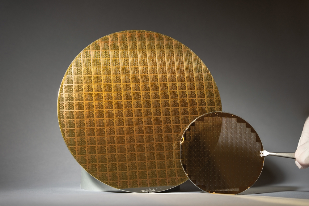
The superiority of single-wafer systems
BY SHINICHI MITANI FROM NUFLARE
Underpinning the long-term growth in global GaN LED revenue has been the penetration of this chip in an increasing number of "killer applications". Backlighting screens and keypads of mobile phones provided the first multi-billion dollar market for this device, and more recently sales have blossomed through the deployment of this chip in the backlighting units of larger screens, such as TVs and tablets, and in general lighting.
As LED revenue has increased, MOCVD growth has shifted to larger diameter formats. High-volume production began on 2-inch sapphire, but during the last decade or so, an increasing proportion of chips have been manufactured on 3-inch, 4-inch and 6-inch sapphire.
Recently, there has also been interest in alternatives to sapphire, including silicon. It is available in larger sizes, such as 200 mm and 300 mm, enabling even higher throughput at the die level. What is more, silicon has a superior thermal conductivity and "processability" to sapphire. These merits have also driven interest in the growth of GaN-on-silicon heterostructures for electronic devices.
Underpinning the long-term growth in global GaN LED revenue has been the penetration of this chip in an increasing number of "killer applications". Backlighting screens and keypads of mobile phones provided the first multi-billion dollar market for this device, and more recently sales have blossomed through the deployment of this chip in the backlighting units of larger screens, such as TVs and tablets, and in general lighting.
As LED revenue has increased, MOCVD growth has shifted to larger diameter formats. High-volume production began on 2-inch sapphire, but during the last decade or so, an increasing proportion of chips have been manufactured on 3-inch, 4-inch and 6-inch sapphire.
Recently, there has also been interest in alternatives to sapphire, including silicon. It is available in larger sizes, such as 200 mm and 300 mm, enabling even higher throughput at the die level. What"s more, silicon has a superior thermal conductivity and "processability" to sapphire. These merits have also driven interest in the growth of GaN-on-silicon heterostructures for electronic devices.
Makers of MOCVD tools have tended to respond to the trend of moving to larger wafers by increasing the capacity of their multi-wafer reactors. But there is another option. It is possible to mirror the path taken in the silicon industry, where an increase in wafer size from 100 mm to 150 mm prompted the majority of tools to switch from multi-wafer/batch tools to single-wafer variants.
At NuFlare Technology, Inc. of Yokohama, Japan, we advocate this approach. We began by developing a series of single-wafer epitaxial tools for silicon and SiC epitaxy, and we expanded our portfolio with the launch of tools for MOCVD growth of 200 mm GaN-on-silicon wafers. Single-wafer tools hold the upper hand over their multi-wafer siblings on several fronts, including the uniformity of the epitaxial film, the width of the process window, and material efficiency. In addition, it takes less time and expense to develop a device structure.
Although these strengths will appeal to GaN-on-silicon chipmakers, they may be reluctant to consider single-wafer tools. That might arise due to a belief that multi-wafer alternatives have lower hardware costs, because the expense associated with a gas-supply unit (gas panel) can be very high. However, we believe that this issue can be addressed by operating single-wafer reactors in parallel. This trims the hardware costs to those of a multi-wafer tool.
![]()
Another attractive attribute of the single-wafer tool is that it eliminates the need to adjust the growth process when scaling-up from a development reactor to a production machine.
The big challenge with a multi-reactor system assembled from single-wafer tools is that to guarantee high productivity, there must be a small difference in the growth characteristics of the various deposition chambers. In other words, the single-wafer reactors must deliver similar growth rates, compositions, doping profiles and so on.
Susceptor-less heatingWe excel in this regard with our showerhead design. It features a unique rotation unit and an approach to wafer heating that is not based on heating of the susceptor (see Figure 1 for a diagram of our reactor). High in-wafer uniformity and material efficiency results from a uniform gas flow and a high-speed wafer rotation, achieved without using a centre-shaft (the typical rotation speed is 1500 rpm, and it can be faster). For growth of a GaN film on a 200 mm wafer, the standard thickness deviation is only 0.5 percent when applying an edge exclusion of 4 mm.
The wafer in our reactor sits on a ring-shaped wafer holder and is directly heated by a heater elements" radiation. Adopting this approach allows us to avoid one of the major weaknesses of the conventional approach to wafer heating "“ a variation in temperature caused by differences in the gap between the wafer and the susceptor, which is the source of heat. Regardless of the reactor geometry, when GaN is grown on a non-native substrate, the difference in thermal expansion between these two materials will cause the wafer to deform during growth. But in a reactor with a susceptor, variations are amplified by differences in temperature that result from differences in the distance between the susceptor and the wafer (see Figure 2).
By using susceptor-less heating, our single-wafer reactors do not suffer from a significant in-wafer temperature distribution. After optimising the heater arrangement, the temperature distribution across a wafer in one of our tools is approximately ± 1°C at 1100°C.
![]()
Figure 2. Heat transfer to a deformed wafer (a) in susceptor-less (direct) heating and (b) from a hot susceptor.
This incredibly high degree of temperature uniformity leads to a very small variation in the photoluminescence spectra across the wafer. For an InGaN/GaN multi-quantum well structure grown at 800°C, the standard deviation in photoluminescence peak wavelength is as small as 1 nm over a 200 mm wafer (average emission wavelength is 450 nm, and edge exclusion 4 mm). Judged another way, the 5 nm bin yield exceeds 95 percent.
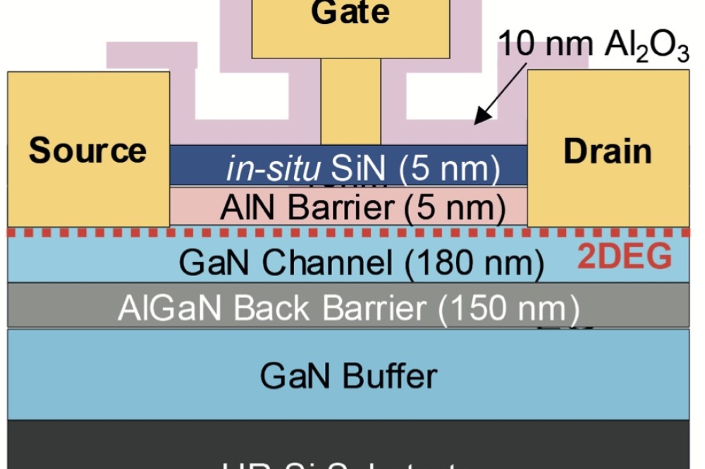
Excellent uniformity can also be seen in HEMT structures produced with our tool. This is evident in values across the wafer for: the full-width at half-maximum of X-ray diffraction peaks; the aluminium composition; and the carrier mobility (see Figure 3).
![]()
Figure 3. The Epirevo G8 is capable of highly uniform film growth. The capability is highlighted by: (a) Full-width half-maximum values of X-ray diffraction peaks of a GaN template on silicon,
![]()
(b) the aluminium concentration of AlGaN, and
![]()
(c), the carrier mobility of HEMT
Our single-wafer reactor"s wide process window is highlighted by measurements on multi-quantum well structures grown at 300 Torr and 500 Torr. At both pressures, indium composition and layer thicknesses are very similar.
Another merit of our approach to wafer heating is that it enables fast temperature ramping. This occurs because the heat capacity of the wafer is far less than that of the massive susceptor. Fast growth times result, which are not just due to a shortening of the time taken to ramp up the wafer prior to growth and to cool it down afterwards "“ there is also less time taken for temperature changes during MOCVD growth. This benefit frequently arises, because different layers are often grown at different temperatures, such as quantum wells and barriers in the active region.
One of the other features of our tool is the gas-phase etching of the wafer-holder. During GaN-on-silicon growth, GaN is also deposited on the reactor. Problems can follow, such as surface damage of the wafer, which results from melt-back etching of silicon by gallium droplets. However, we address these issues with our reactor: deposition of GaN is limited to the wafer-holder and avoided on the reactor wall, thanks to the well controlled gas-flow provided by on elaborately designed showerhead; and GaN that adheres to the wafer-holder is removed after every run to ensure repeatable GaN-on-silicon deposition. This cleaning process involves introducing etching gas into the reactor and heating a dummy wafer on the wafer-holder. To minimise surface defects caused by manual loading, our tools employ cassette-to-cassette automatic loading of wafers. Note that this is a basic option on our tools.
Matching reactorsA high throughput is only possible when our reactors are used in parallel. To ensure a high yield, the set of reactors that are employed must be matched to one another.
![]()
Figure 4. Radial distribution of the pair thickness, and the indium concentration, of multi-quantum wells grown at 300 Torr and 500 Torr.
The first step that we made towards this goal involved designing a gas supplying unit that delivers an equal amount of material to every reactor. One gas panel is used for the main raw materials. A master-slave, mass-flow controller gas distribution technology divides each material gas flow into an equal amount of subflows, which is fed to each reactor. Our second step for ensuring reactor-to-reactor consistency involves compensating for the small variations in film thickness and alloy composition between each deposition chamber. In the case of InGaN/GaN multi-quantum wells, success resulted from independent tuning of the growth parameters for each reactor (see Figure 5 for the results on four wafers grown in four different reactors).
![]()
Figure 5. Radial distribution of the pair thickness, and the indium concentration, of multi-quantum wells of four wafers grown in different reactors in a run.
With reactor-to-reactor consistency assured, process engineers can take advantage of the greater flexibility of a set of single-wafer reactors, rather than a multi-wafer tool. When developing devices, their needs can be satisfied with one reactor with one gas panel. Adding a second reactor and a gas panel for the new reactor to the existing system offers an easy route to higher throughput during the latter stages of development. For production, the system can then be upgraded to four reactors sharing a single gas panel (see Figure 6).
Having proven the capability of our tool for manufacturing LEDs and electronic devices, we are now evaluating its suitability for producing other classes of device.
To satisfy the demands of all of our customers, we must strive to continually improve the performance of our tool. Efforts in this direction include the development of new recipes, such as those for: the growth of InGaN/GaN multi-quantum wells at higher pressures, and the optimisation of buffer layers, doping profiles and device structures. We are also working to increase the time between maintenance, and offer a reactor for 300 mm wafers. The performance of the latter can only be confirmed through a joint development with our customers.
![]()
Figure 6. Examples of system configurations: (a) simple configuration of process module and gas panel (PM + GP); (b) independent, two simple systems of PM + GP with a transfer module (TM); and (c) 4 PMs + GP system for production.


