Technical Insight
Slashing the cost of the GaN substrate
Production of affordable, high-quality GaN substrates could result from HVPE of GaN on a native surface
BY MALGORZATA IWINSKA FROM THE INSTITUTE OF HIGH PRESSURE PHYSICS, POLISH ACADEMY OF SCIENCES


Imagine, for a moment, that you could make thousands of substrates from a high-quality GaN boule just a few millimetres thick. Such a feat is conceivable, requiring resulting wafers to be as thin as 150 nm.
Armed with this incredibly thin, very high-quality substrate, you would have the potential to revolutionise GaN chip production. Thanks to homo-epitaxy, the quality of the epilayer would match that of its foundation, making this approach ideal for growing of bulk GaN and for the production of high-quality devices. Note that these substrates would be in high demand, as alternatives to GaN are not an option for the manufacture of GaN lasers and vertical high-power transistors, because they lead to imperfections that degrade device performance.
Unfortunately, such substrates are just a dream for today's chipmakers, who must make do with GaN substrates that are pricey, limited in availability, and have a quality that depends on the retail price. If they want the best material, they must seek substrates produced by the ammonothermal method, but diameters are limited to 2-inch. HVPE can provide cheaper substrates with diameters of up to 4-inch, but crystallographic quality is far worse.
What is encouraging, however, is that in the research community, a GaN layer just 150 nm-thick has been used to form a free-standing, 1 mm-thick HVPE-grown GaN crystal. This triumph has been achieved by our team at the Institute of High Pressure Physics, Polish Academy of Sciences, working within a European project called the Development of Advanced GaN substrates & Technologies (AGATE). This effort, led by the French firm Soitec, a worldwide leader in engineering substrates, opens a new path to the production of GaN substrates and the multiplication of high-quality GaN crystals.
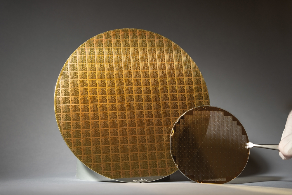
The GaN-based substrates that we use for our work, which have diameters that can reach 6-inches, are prepared by Soitec. These advanced substrates are similar to that of a template, but they have a unique feature − a very thin GaN layer that has been separated from starting material by ion implantation.
Today, the origin of this GaN layer is an MOCVD-grown, GaN-on-sapphire template. But this advanced substrate can be improved by turning to high-quality GaN wafers as the starting material. If this route is taken, the final product is no longer limited by the quality of the GaN grown on a different foundation.
To create an advanced substrate, a silicon-oxide-based layer is used to bond GaN to a new handler that is just a few hundred microns thick. Governing the selection of the handler are the desired properties of the advanced substrate. There are many different possibilities for the handler, and we have chosen two kinds of Ga-polar advanced substrates as seeds for our HVPE growth. They are the relatively common combination of GaN-on-sapphire, and the more esoteric pairing, GaN-on-molybdenum. We have chosen molybdenum because it has a very good thermal match to GaN (see Figure 1 for the thermal coefficients of GaN, sapphire and molybdenum).
Figure 1. In terms of the coefficient of thermal expansion, molybdenum is a far better match for GaN than sapphire. Red lines are a fit performed and extrapolated to higher temperatures (courtesy of M. Seiss, Plansee).
Figure 2. (top) The HVPE process used by the team from the Institute of High Pressure Physics, Polish Academy of Sciences, involves: I, forming an opening in a titanium mask; II, decomposing a GaN layer beneath the mask to form voids (this is critical for subsequent self-lift-off); III, three-dimensional GaN growth in openings in the mask "“ pyramids appear above the titanium mask; IV, coalescence of GaN, involving three-dimensional growth; and V, two-dimensional growth of GaN after full coalescence. (bottom) A cross-sectional scanning electron microscopy image of GaN that has been grown on a mask by HVPE.
The HVPE method that we use to deposit GaN involves crystallization from the gas phase. At relatively high temperatures, such as 1100 °C, gallium chloride reacts with ammonia to form GaN.
We are by no means alone in using HVPE to create layers of GaN. Due to a lack of native GaN, often the starting point is a foreign wafer, such as an MOCVD-grown, GaN-on-sapphire template. The downsides of working with foreign wafers are the mismatches in lattice constants and thermal expansion between the seed and the crystallized material. These differences lead to significant strain, and cracking can result when the thickness of the layer exceeds a few hundred microns.
One way to minimize this stress is to intentionally introduce voids and create a rough layer at the onset of growth. To realise this and promote three-dimensional growth, the seeds must be specially prepared prior to HVPE growth.
We have done this, depositing a 20 nm-thick titanium mask on the GaN layer, and then using photolithography to create round openings with sizes of 3-10 μm, separated by 9-16 μm. A great strength of this approach, which is similar to the void-assisted separation technology developed at Hitachi Cable, is that it can form un-cracked GaN crystals via a self-lift-off process.
With our approach, the surface of the processed wafer is prepared for growth by controlling the decomposition of the GaN layer beneath the titanium mask. Get this right and GaN can deteriorate in a uniform, non-excessive manner across the entire surface. Once this is accomplished, growth begins, with GaN initially crystallizing in the openings of the mask, before pyramids start to appear. Coalescence of GaN then takes place above the titanium layer, with growth proceeding in a three-dimensional mode until full coalescence.
At that point in the growth there is a switch to a two-dimensional mode, with macrostep flow. This occurs on either the entire surface, or from the centres of hillocks already formed on the surface. Initially, the surface contains a large number of hillocks, but they "˜consume' one another to create a surface with either just one of them, or possibly a few.
The crucial step in this entire process is the decomposition of the GaN layer. It is this that creates the voids between the seed and the new-grown material, and ultimately enables the self-lift-off process during wafer cool down. The quality of the HVPE crystal is also influenced by three-dimensional GaN growth. This creates layers that can realise a relatively low threading dislocation density, because dislocations can propagate in directions other than that of the growth.
As our HVPE reactors are designed to accommodate seeds with diameters of up to 2-inch, we have prepared 1-inch and 1.5-inch samples from 4-inch GaN-on-sapphire and GaN-on-molybdenum wafers. After placing a mask on the GaN surface, we have used HVPE to grow GaN layers with a thickness of up to 1 mm. Finally, we prepared substrates for epitaxy from the obtained crystals.
Visual inspection of these crystals reveals that they are crack-free (see Figure 3), implying that the self-lift-off process occurred during the cool-down phase. As expected, the crystals have the desired c-plane growth morphology. Hillocks, with macrosteps flowing from their sides, provide the growth centres.
Figure 3. Free standing, HVPE-grown GaN from: (top) a 1-inch, GaN-on-sapphire seed and (bottom) a 1.5-inch, GaN-on-molybdenum seed.
Etching the surfaces of these samples enabled an estimate of the threading dislocation density. In both types of seed, this density is typically 5 x 108 cm-2; while in HVPE-grown crystals, the threading dislocation density is far lower, never exceeding 1 x 107 cm-2.
We have scrutinised the structural properties of our crystals by X-ray diffraction. For GaN-on-molybdenum, the full-width-at-half-maximum for the rocking curve of the symmetric (002) reflection is 380 arcsec, and for GaN-on-sapphire it is just 180 arcsec. Both these values are much smaller than those for the used seeds: 645 arcsec for GaN-on-sapphire, and 755 arcsec for GaN-on-molybdenum.
In the absence of intentional doping in the growth process, the crystals have a very low level of impurities. The main dopant, oxygen, has a content below 1017 cm-3, leading to a comparable value for electron concentration.
Figure 4. (a) A free-standing, as-grown crystal from a 1-inch GaN-on-sapphire seed, with a hillock visible on the surface. (b) A free-standing, as-grown crystal from 1.5-inch GaN-on-molybdenum seed, with many hillocks on the surface; pits visible on the surface are shallow and are removed during surface preparation. (c) A differential interference contrast image of the morphology. The hillock growth mode and macrosteps are visible on the side of the hillock.
Figure 5. Wafers prepared from HVPE-grown GaN, grown on: (a) a 1.5-inch, GaN-on-molybdenum and (b) a 1-inch GaN-on-sapphire.
For optoelectronic devices, and electronic ones with a vertical conduction path, an increase in the free-carrier concentration is required. We achieve this by doping with silicon, a process performed on a 1-inch GaN-on-sapphire seed. HVPE growth produced 300 μm of undoped GaN, followed by 500 μm of GaN that is doped with silicon. A free-standing crystal containing both of these layers is created by self-lift-off.
The characteristics of our doped wafer include a threading dislocation density in the doped material of 7 x 106 cm-2, and a concentration of silicon of 5-7 x 1018 cm-3, according to secondary ion mass spectrometry. The presence of silicon increased the free-carrier concentration, with Raman spectroscopy indicating a value of 4 x 1018 cm-3, and verification from Hall measurements suggesting 5.7 x 1018 cm-3. Substrates with this level of free-carrier concentration are suitable for making laser diodes.
Figure 6. (a) An atomic force microscopy image of a HVPE-grown, silicon-doped GaN substrate. The root-mean-square surface roughness is 0.146 nm (courtesy of A. Feduniewicz-Zmuda, IHPP PAS). (b) Light-current characteristics of a laser diode formed on HVPE-GaN, grown on GaN-on-sapphire (courtesy of C. Skierbiszewski, IHPP PAS).
We have produced wafers from our GaN crystals (see Figure 5 for examples). They include a doped wafer that is a suitable foundation for making a laser diode. This wafer's Ga-polar face has been treated by mechanical and chemo-mechanical polishing to provide a surface suitable for epitaxy. According to atomic force microscopy, the surface has bilayer steps, and a root-mean-square roughness of 0.146 nm (see Figure 6). Note that the equivalent figure for the GaN starting layer is 0.197 nm.
A 450 nm, CW laser has been formed via MBE growth on our doped substrate. This device has a threshold current of 250 mA and a slope efficiency of 0.2 W/A. These values are not as good as those of commercially available devices, but that could be due to the design of our heterostructure, which was a novel architecture under evaluation.
Figure 7. 2-inch, free-standing HVPE-grown GaN with a high crystal quality. The threading dislocation density is only 5 x 104 cm-2.
Our work, which is on-going, is an important step towards the fabrication of affordable, high-quality GaN substrates. We have shown that by starting with advanced substrates, formed with Soitec's Smart Cut technology, HVPE can be used to grow thick layers of GaN, which have a crystal quality that is superior to that of the starting layer. Although the handler materials that we have used "“ sapphire and molybdenum "“ were selected for their similar thermal expansion and lattice constant parameters to GaN, even high crystal quality and better devices should result from using a GaN handler.
That approach is our ultimate goal. It will involve separation and transfer of GaN layers from high-quality GaN crystals to a GaN handler of lower quality, such as free-standing GaN that is grown on the likes of an MOCVD-grown, GaN-on-sapphire template. We are already laying the foundation for this, with the production of 2-inch high-quality, HVPE-GaN (see Figure 7). This is an attractive approach that we will pursue to multiply the number of high-quality GaN substrates.


