
Turbo-charging transmission with digital signal processing
To ease the strain on optical infrastructure, leading communication systems are combining high-quality InP lasers, detectors and modulators with advances in digital signal processing
BY GEOFF BENNETT, YUEJIAN WU, AND HAN SUN FROM INFINERA
KNOWN AS ‘Motormouth’, the New Yorker John Moschitta Jr., who can hit 586 words per minute in full flow, is generally regarded as the fastest talker in the world. Note that we say ‘generally’, because two people have gone faster – but when you watch them in slow-motion, you’ll see that they make mistakes or are incomprehensible.
Optical transmission shares this problem – that is, as the rate of information transfer increases, so does the difficulty of reliable reception. But, unlike the human ear, designers of optical transmission systems implement powerful digital signal processor (DSP) techniques to clean up the signal and dramatically improve the reliability of data reception. Here, we review the challenges of high-speed transmission, before explaining how Infinera has used DSP to revolutionise optical communication.
Let us begin by considering a simplified long-haul optical transmission link; it could operate between two cities or even under the ocean. For this example, depicted in Figure 1, a pair of IP routers are connected over blue transceivers. At each end, a terminal system multiplexes and demultiplexes optical signals from lasers emitting at slightly different wavelengths, and directs them down a single pair of fibres. Note that with this well-known technique, referred to as dense wavelength-division multiplexing or DWDM, one fibre usually provides the transmit path and the other the receive path.
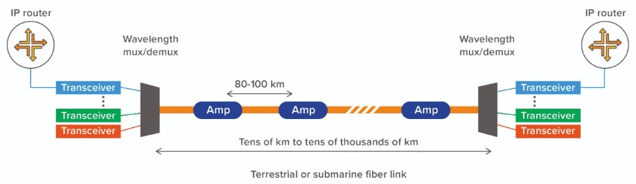
Figure 1. Elements of a typical long-haul or submarine optical network link.
The great strength of this parallel DWDM approach is that it allows an increase in the total optical fibre capacity independent of the scaling of the individual wavelength data rates. Thanks to this, the DWDM transmission industry has increased total fibre capacity by a factor of 200 in the past 20 years, spurred on by an insatiable desire for ever-higher-speed internet connectivity.
During this tremendous increase over the last two decades, there have been two dramatic jumps around 2009: back then per-wavelength and per-fibre capacity first shot-up by a factor of four, to 40G per wavelength, before then climbing by a factor of 10 or more. Underpinning this expansion, which marked an inflection point in optical capacity growth, came a move to coherent transmission with advanced digital signal processing. Since then, per-wavelength data rates have steadily increased by another factor of eight, with current leading-edge products operating at 800 Gbit/s.

Figure 2.Schematic of coherent transceiver showing transmit and receive DSP location.
Prior to 2009, long-distance transmission tended to involve simple on/off keying in the transmitter. At the other end of the fibre, a direct photodetector converted this very ‘binary-looking’ modulation back into an electrical signal. We refer to this form of transmission as intensity modulation with direct detection. One of its key traits is that it features a direct detector, operating on a square law relationship to the strength of the received modulation symbols. By taking this approach, it is very difficult to use digital signal processing to compensate for linear optical impairments, issues that we will now outline.
Just as John Moschitta’s rivals introduced ‘noise’ – that is, errors – into attempts to break the words-per-minute record, an optical fibre link can suffer from noise that comes from a number of different sources. As production methods evolve, some of these improve over time, such as the quality of the laser and the noise level of the amplifiers.
Other signal distortion effects can be compensated for with powerful mathematical techniques, so long as we can implement a linear detector. These include: dispersion effects, particularly chromatic dispersion and polarization-mode dispersion; high-order modulation issues, which can be addressed using a technique called probabilistic constellation shaping; and nonlinear effects, which are triggered by high optical power levels in the fibre.
The first of these, dispersion, is associated with the spreading out of the modulation symbol on its journey along the fibre. If you fail to reverse that effect, the sequential symbols will run into one another, preventing the receiver from correctly interpreting the value of a given symbol. This is analogous to one of Moschitta’s rivals slurring their words, so that they run together, making it harder to understand where one word ends and another begins. Chromatic dispersion stems from the different frequencies of the modulation symbols, while polarization-mode dispersion comes from the vertical and horizontal polarizations of the modulation symbol travelling at slightly different speeds.
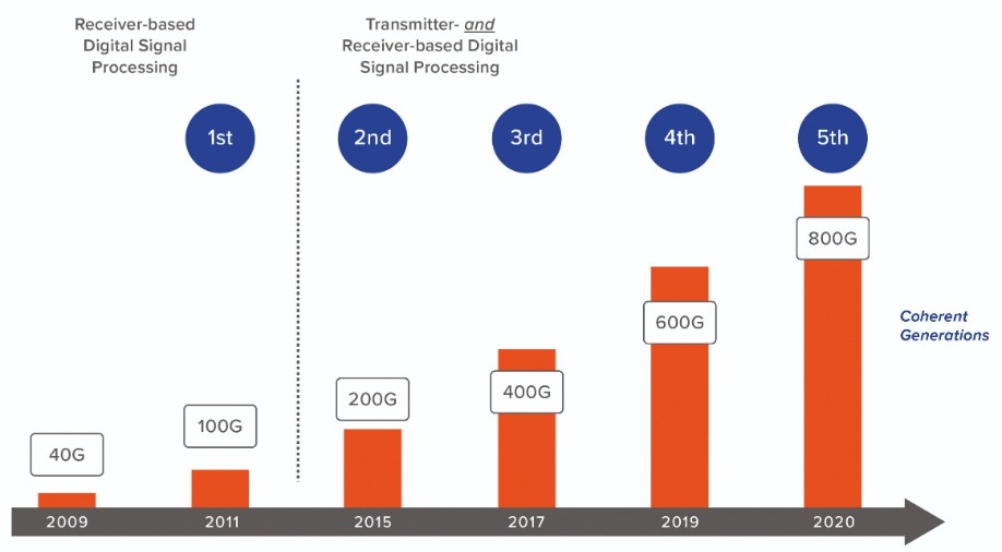
Figure 3. Evolution of headline data rate for coherent transmission.
Non-linear effects, the third form of signal distortion that we list, are introduced when the optical power level in a fibre exceeds a certain threshold. This issue is similar to that of Moschitta’s rivals talking into the microphone so loudly that the listener starts to hear distortion.
Coherent optical transceivers
In 2010 the optical industry began to deploy a radically different approach for sending and receiving information – phase modulation with coherent detection (see Figure 2 for a simplified schematic of the latest generation of coherent transceiver). While the first generation of coherent transceivers had processing only in the receiver, subsequent generations include both transmitter and receiver-based processing.
The laser in the transmitter shines constantly – creating an optical carrier. The digital electronic signal is sent into the transmit portion of the DSP for pre-processing, then the processed digital signal is sent to a high-speed digital-to-analogue converter (DAC), with the resulting analogue signal applied to a Mach-Zehnder phase modulator, which applies this signal to the optical carrier. Note that by sending separate modulation signals on the X and Y polarizations of the light, the capacity of the modulation symbol is doubled. After this, the optical signal, containing a stream of high-speed modulation symbols, is launched into the fibre for its journey of many kilometres.
Within the receiver, there is a local oscillator laser with a continuous output, tuned to the wavelength to be received. The local laser output is mixed with the incoming signal from a fiber, and the mixed signal is then split into X and Y polarizations. The parallel signals enter a phase demodulator array, formed from adjustable Mach-Zehnder elements. This results in the generation of a massively complex set of interference patterns that would be changing so quickly they would appear as a constant light to the human eye. A parallel set of photodetectors captures the interference patterns, converting the analogue optical signals to analogue electrical signals that are boosted by a transimpedance amplifier. These stronger signals are sampled and digitized in an analogue-to-digital converter (ADC), with the resulting digitalised signal passed to the receiver DSP and processed to produce a clean, reliable bit stream.

Unlike a pure electronic circuit, the optical transceiver makes use of a range of semiconductor materials, using the most appropriate one for each task (these materials are colour-coded in Figure 2).
Regular readers will know that InP is the ideal material for creating high-performance lasers and photodetectors at wavelengths employed for long-distance optical transmission, typically the domain that spans 1530 nm to 1625 nm. InP is also the best choice for the modulators at these data rates. Due to this dual role, it is possible to use InP for all the optical functions for both transmit and receive, forming a single photonic integrated circuit (PIC). SiGe is the material used to produce transimpedance amplifiers that deliver consistent amplification over wide bandwidth and a low noise level, while silicon CMOS is employed for making application-specific integrated circuits (ASICs) used for the DAC, ADC, and DSP functions. In Figure 2, we show that the transmit and receive DSP circuits are implemented on a single ASIC chip. Using this architecture, at least one of the latest 800 Gbit/s implementations is made up of more than 5 billion transistors.
Materials aside, those of you with a background in radio communication will be familiar with the approach that we shall now describe. At the transmitter, instead of sending an on/off signal, we use a phase modulator to encode digital signals as a set of different phase states. And at the receiver, rather than directly interpreting the on/off signal without any processing, we use a coherent detector – this consists of a reference laser, known as the local oscillator, the signal of which is mixed with the data signal. When used in radio systems, a local oscillator allows tuning in to a specific radio station, out of perhaps dozens of radio stations that have signals passing through the detector.
In optical transmission, the situation is slightly different, as we have already separated the particular wavelength we wish to receive. In this case, the local oscillator acts as a very low-noise amplifier, and the resulting phase demodulator is a linear detector. Having a linear detector is a tremendous asset, allowing us to finally bring the power of digital signal processing to bear on the problem of compensation of linear channel impairments such as chromatic dispersion and polarization-mode dispersion.
Advancing DSPs
While coherent detection may be familiar to anyone from the radio world, and DSPs to fans of DAB radios, the sample rates and processing power required to process high-speed optical signals are on a totally different scale. To put this in perspective, for CD quality audio the accepted sample rate is 44.1 kHz, while a modern coherent transponder operates about two million times faster at well above 100 GHz sampling rate to correctly recover transmitted information from signal symbol rates close to 100 gigabaud.
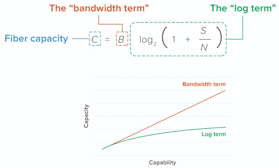
Figure 4: The Shannon equation and the diminishing returns in fiber capacity from future coherent transceiver enhancement
The key to realising the processing rates needed for high-speed optical transmission is to use the very latest process node sizes for a given coherent generation. Progress is fast, evolving from 100 Gbit/s transponders with around 300 million gates in 2010 to 800 Gbit/s today, using over 5 billion gates (see Figure 3 for the impact of this evolution on wavelength data rates).
One downside of coherent processing is that it consumes a significant electrical power budget. Consequently, in order to maintain stable operation, heat must be pulled from the chips. Historically, Moore’s Law is to thank for providing a pathway to reducing electrical power, per unit processing power. While there are various forms of this law, they all refer to a trend of doubling certain chip metrics within a given time period. This advance leads to a faster processing at lower power. In the case of the ASIC technology used in coherent DSPs, as each generation of process node delivers roughly a 0.7 times reduction, two generations of progress are needed to double the DSP bandwidth for the same power consumption.
Improvements are now more challenging. The recent move from 16 nm feature sizes in fourth-generation transceivers to 7 nm in the current fifth-generation transceivers delivered around a 51 percent saving in power consumption per unit processing speed. In comparison, there will only be a power saving of around 30 percent when moving from 7 nm to 5 nm.
Detailed predictions of likely developments in electronic devices and systems are presented in the IEEE International Roadmap for Devices and Systems. One of the goals of this roadmap, which includes the ASIC technology used for DSPs, is to identify key trends related to devices, systems, and all related technologies over the next 15 years. Additional aims are to determine generic devices’ and systems’ needs, challenges, potential solutions, and opportunities for innovation; and to encourage related activities worldwide through collaborative events, such as related IEEE conferences and roadmap workshops.
Right now, there is no clear solution to the slowing down of power reduction. An imperfect option would be to design a MOSFET with a steep sub-threshold, but while this would result in more efficient power consumption, it would go hand-in-hand with a slower processing rate for serial operations within any pathway through the DSP. The general consensus within the semiconductor community is that a new DSP architecture is required to maintain the historical rate of progress.
Capacity challenges
Valuable contributions from Bell Labs to the development of DSP are not limited to the work of Harry Nyquist. Contemporary Claude Shannon made other contributions to information theory, including developing an equation that allows us to calculate the maximum capacity for a given communication channel. Back in the 1940s, Shannon would have been thinking of a copper telephone wire or wireless telegraphy channels, but now, in the era of optical communication, it is used when considering optical fibres.
The Shannon equation, in simplified form, is shown in Figure 4. On the left is C, representing the channel capacity, and on the right are two terms: one represents the bandwidth of the channel, and the other is related to the signal-to-noise ratio. For optical transmission, the bandwidth is the range of wavelengths used for amplifying the signals as they travel along the fibre. This is usually the C-band, which spans 1535 nm to 1565 nm, and may sometimes also include the L-band, which is the domain from 1565 nm to 1625 nm. Within the log term, there is a function based on the signal (S)-to-noise (N) ratio, which is often summarized as ‘bits per channel utilization’.
Included in Figure 4 is an illustration of how channel capacity, shown on the vertical axis, increases for a given rate of improvement in either the bandwidth or S/N ratio. There is a better return for increases in bandwidth, because S/N is within a log function, so improvement in capacity tails off. This implies that there are diminishing returns when efforts are directed at improving amplifier noise levels, fibre quality, and in particular coherent modem functionality, because they all address the S/N ratio.
The good news is that there are a range of options for increasing bandwidth. Consider, for example, the C-band. Bandwidth can be increased by turning to Super C-band amplifiers – this boosts amplified bandwidth by a little over 20 percent – and also by using the L-band (note that the L-band is almost never deployed on its own – it is always deployed with C-band). Compared to a conventional C-band system, one that amplifies Super C- and Super L-bands delivers almost three times the bandwidth.
These options are focused on terrestrial networks, where it is relatively easy to deliver electrical power to an amplifier chain. That’s not the case in submarine cables, which contain a thick conductive layer that delivers up to 15 kV to each end, to power the amplifier. In a submarine cable, it is often the ability to deliver power to an amplifier chain that limits the number of fibre pairs.
An alternative submarine cable architecture, now being deployed in some newer cables, is space-division multiplexing. As this reduces amplifier power consumption, it sacrifices capacity per fibre pair, but trades this for an increase in the number of fibre pairs. The change is beneficial, increasing the capacity for the cable. An additional move in this direction is the evolution of coherent transponders, which are expected to limit the additional optical performance in exchange for a smaller module size with lower power consumption. This process will be driven by 5 nm or smaller DSP process nodes.
Whether the networks are terrestrial, or they run along the sea bed, there is plenty of scope to maintain optical transmission capacity in the short to medium term.
For the past decade, high-speed optical transmission has relied on the power of advanced digital signal processing to increase data rates per wavelength, and ultimately the total fibre capacity of long-distance and submarine communication systems. While there are challenges to both DSP scaling and fibre transmission limits, strategies and solutions are available for maintaining growth in capacity, while driving down the cost of moving information around the world.


