Integrating microLEDs with advanced CMOS

Bonding 300 mm GaN-on-silicon LED wafers to CMOS backplanes of the same size offers the best approach for producing displays that have a microLED pitch of just a few microns.
BY Soeren Steudel FROM MICLEDI Microdisplays
For the last five years or so microLED manufacturing has been a very hot topic within the display industry. It’s been high on the agenda at leading display events, such as Display Week, with the focus on flat panel manufacturing of various displays, ranging in size from smart watches to mobile phones and TVs. For this technology, efforts at scaling manufacture are thwarted by challenges associated with mass transfer of the microLED, as well as the repair of defective die.
A new set of issues are faced when considering microLEDs for microdisplay applications, like augmented-reality (AR) glasses. One approach to making a microLED-based display module for that type of application involves uniting microLEDs and CMOS backplane ASICs, which control and drive the microLEDs. This approach eliminates issues associated with mass transfer, but comes up against a different set of obstacles. Consider the primary application on the horizon for this technology, AR glasses: there’s a need for a brightness exceeding 1 Mnits, pixel pitches below 3 mm, a resolution of up to 2K and beyond, ultra-low power consumption and acceptable cost, all in a light-weight module.
As of today, none of these specifications are being met by existing microdisplay manufacturing methods. But progress is underway. The chipmaker JBD of Shanghai, China, has introduced several impressive prototypes and is delivering modest volumes. However, high-volume manufacturing is elusive. Meanwhile, our company, MICLEDI Microdisplays of Leuven, Belgium, is making good strides on addressing issues that limit the brightness and resolution of microLED displays. To this end, we are developing an approach that’s needed to deliver high-volume, low-cost manufacturing. Read on to discover the details of the challenges we face and our compelling solutions.

Figure 1. Light-outcoupling in a planar microLED with (a) small pixel versus a (b) tight-pitched array.
Brightness and efficiency
One weakness of AR glasses is their very substantial optical losses. The extent of this is governed by the implementation, but often less than just 1 percent of the photons emitted by the display arrive in the eye. Due to these staggering losses, displays have to generate up to 10 million nits of white light to support outdoor usage with high-transparency glasses.
A comparable microOLED display, which is a rival technology to the microLED display, can achieve in the best case 20 knits for green, even though the efficiency number for OLED will be better than for microLED. A summary of the state-of-the-art by Yole Intelligence, the French market analyst, in 2019, showed efficiency numbers for OLED (RGB – 22 percent, 22 percent, 7 percent), versus the 5 mm microLED (RGB – 7 percent, 15 percent, 25 percent). Note that these figures are far below the values for the internal quantum efficiency of the GaN LED, which has a typical value of 85 percent in the blue, 60 percent in the green and less than 30 percent in the red.
Efficiency losses at scaled dimension are mostly due to optical outcoupling and, to a lesser extent, electrical losses due to defects at the mesa sidewalls, leading to a high amount of non-radiative recombination and an increased leakage current. The light-outcoupling in a planar LED is limited by the angle of internal reflection from the high index compound semiconductor material into air. This automatically means that for a GaN LED, less than 10 percent of the light can be extracted with a perfect backside mirror, neglecting interference effects. For larger LEDs with dimensions greater than 100 mm, surface texturing is applied with a very good backside mirror. This enables every photon to have multiple chances of escaping under different angles, leading to a theoretical light extraction efficiency of 75 percent. Surface texturing is not a solution for microLEDs with dimensions below 5 mm since there is no space for the photon to undergo multiple reflections.

Figure 2. ((left) Field-of-view (FOV) plotted as a function of pixel number for different angular resolutions (Mpixel refers to 1 pixel with a red-green-blue sub-pixel with a display ratio 1:1); (right) Die size for different sub-pixel pitches (assuming an advanced node CMOS (<45nm) with a framebuffer and a display ratio 16:9).
It’s also worth noting that the efficiencies provided by Yole are very optimistic, and only apply to individual LEDs spaced very far apart. This is illustrated in Figure 1, which considers different spacing scenarios. In microLEDs, the direct emission through the transparent front-side contact is very low, typically below 10 percent – but extraction can be boosted by adding a sidewall mirror that extracts light beyond the angle of internal reflection. However, when packing microLEDs closer together to ensure a higher pitch, any type of sidewall mirror is less effective. Due to this impediment, the external quantum efficiency of microLEDs in very small displays is expected to be limited to no more than 8 percent, unless there is a shift to a directional emitter architecture.
So, given these low values for microLED efficiency, these devices are still seen as a viable alternative to OLEDs, because they have a vastly superior current handling capability. By being able to sustain a current density that is more than a thousand times higher than an OLED can handle, these GaN-based devices can deliver the target brightness.
 Figure 3. Die yield versus field-of-view (FOV) for different sub-pixel pitches. (left) assumes RGB pixel-by-pixel; (right) assumes RGB die-by-die.
Display size and resolution
Two questions for any display based on the microLED are: What is its required size? And what resolution is appropriate? To answer them, it’s imperative to consider the capabilities of the human eye. In both the green and blue spectral domain, the human eye has an angular resolution of 60 pixels per degree. We noted this figure when considering the targeted field-of-view for AR glasses. As one would expect, the number of pixels in a display must increase when increasing the field of view, or the angular resolution (see Figure 2, left). In some current commercial headsets, where the system supports a full high-definition display, there is a limited field-of-view of 50°. One benefit of moving from 5 mm to 1 mm microLEDs is that they can offer a larger field-of-view from the same display size (see Figure 2, right).
While this level of miniaturisation is appealing, it is far from easy to realise with routine success. Even the manufacture of a full high-definition display with 5 mm pitch approaches the limits of the reticule size of the exposure tool. Operating near this limit impacts manufacturability and yield.
We have calculated the impact of yield for different pitches. According to our manufacturing yield model (see Figure 3, left) – that assumes red, green and blue microLEDs co-integrated side-by-side – even when the target resolution is reduced to only 40 pixels per degree, a pitch of less than 3 mm is needed to exceed a 50 percent yield.
It is possible to significantly relax these conditions by manufacturing three different colours of emitter independently, before bringing them together with an optical combiner (see Figure 3, right). This gets far closer to the yield model of an incumbent colour display technology, known as the sequential liquid-crystal-on-silicon display.
 Figure 4. Overview of microLED-on-CMOS integration schemes.
Manufacturability
Over the last ten years several groups have scaled the dimensions of the microLED below 1 mm. However, for these researchers, it is often only an afterthought to consider the integration of the LED pixel with the CMOS driver circuit, commonly known as the ‘backplane’ IC.
A number of approaches may be taken to realise this integration (options are summarised in Figure 4). One is die-to-wafer transfer, accomplished by either transferring and placing pixels one at a time to create an array of red, green and blue emitters, or by bonding the full array as an individual chiplet. Both these die-to-wafer transfers employ indium bumps, a technology that’s been used in the mass production of infrared imagers for more than 20 years. Another strength of die-to-wafer transfer is that it allows the CMOS backplane to be made in a standard CMOS fab, and the front-plane diode array in a compound semiconductor fab – with each fab tailored to the particular wafer size and using dedicated tool sets. With this approach, production scales well to a pitch of 10 mm, before significant yield losses arise. There are also other die-to-wafer approaches with other types of micro-bumps, as well as hybrid bonding.
For military and space applications, ultraviolet and infrared imagers have been produced with pitches as low as 4 mm using die-to-wafer bonding. However, yield is very low – it’s unacceptable for the display industry. So, for microLED displays, a full wafer-to-wafer approach is needed to go below a 10 µm pitch and combine the LED with the backplane. If wafer-to-wafer bonding is to be employed alongside a sequential 3D approach, the LED array wafer and the CMOS wafer must be the same size. That presents a problem: as microLEDs require more complex driving and compensation schemes compared with OLED displays, such as the inclusion of a framebuffer, the accompanying silicon circuitry must be made on 300 mm wafers, using advanced nodes that are well below 45 nm. As no 300 mm compound semiconductor epiwafers are produced in volume, efforts are currently directed at resizing (coring) larger CMOS wafers to 100 mm or 150 mm in diameter, resulting in costly wafer area loss. Progress with hybrid bonding is also hampered by the need for extreme surface planarity, as well as a very low wafer bow and generally low stress. All these requirements are challenging to fulfil with nearly every compound semiconductor stack deposited by heteroepitaxy.

Figure 5. Manufacturing flow from 300 mm compound semiconductor reconstitution to hybrid bonding of a diode array with an advanced node CMOS.
What’s encouraging is that production processes to stack silicon wafers are already in use, combining sequential 3D structures with through-substrate vias and wafer-to-wafer hybrid bonding. The latter is commonly employed for producing backside-illuminated imagers with a pitch down to 3 mm, and is used in R&D departments to unite 300 mm wafers at a pitch down to 1 mm with overlays less than 200 nm.
Display integration
Our company, a spin-out of imec that launched in 2019, is on a mission to solve the manufacturability and yield issues outlined above. While developing our display technology, the decisions that we have taken have adhered to the three following premises: our integration flow is developed on 300 mm production equipment, so that it can be transferred to a CMOS foundry; the materials we select are as compatible as possible with the contamination and waste management protocols of advanced CMOS fabs – so that means no silver, gold or GaAs; and that, as much as possible, established process steps and modules are adopted that have delivered high yields when manufacturing other products.
With these requirements at the forefront of our mind, we have developed an LED integration process that is very similar to that employed for making 3D backside-illuminated imagers. However, in our case we replace the silicon-photodiode wafers with that populated by GaN diodes (see Figure 5). We have overcome the limitations of the starting GaN material, such as its small size, significant stress and bow, and its high particle density, by sourcing best-in-class commercial epiwafers, screened from multiple vendors. Epi-dice are cut to the size of the final display, such as 4 mm by 6 mm for a full high-definition, prior to redistribution across a
blank silicon wafer. Following removal and planarization of the epi-growth substrate and the buffer layer, we produce a stress-free 300 mm-diameter structure with known good epi-die pre-selected, so that only a 1.5 mm-thick GaN stack remains, featuring an active region sandwiched between doped layers (see Figure 6 (a)). From a wafer-handling perspective, this reconstituted wafer behaves like a silicon-wafer.
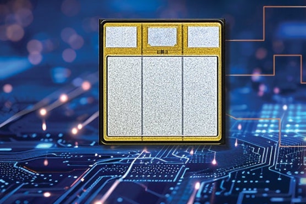
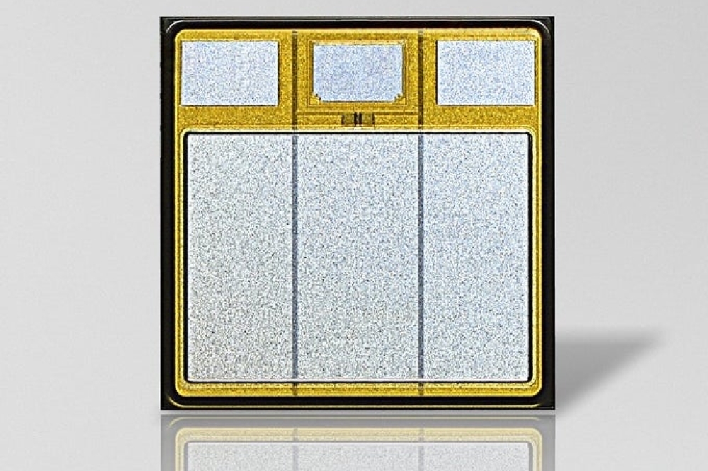
Figure 6. Images of a 300 mm LED wafer (a) after GaN reconstitution; (b) after a full wafer-to-wafer integration scheme. (c) packaged die. (d) a 480 x 320 passive array with 9150 ppi.
Processing creates LEDs with a 3 mm pitch on a 300 mm wafer. Subsequent wafer-to-wafer hybrid bonding unites this wafer to a 300 mm CMOS backplane ASIC wafer with an alignment accuracy tighter than 250 nm. For our initial process development, device characterization and sampling, we used a silicon wafer with just a few metal layers, limiting operation to passive control of the matrix arrays (see Figure 6 (d) for wafer-level testing of a passive array of 480 pixels by 320 pixels; Figure 6 (c) for an image of packaged die; and Figure 6 (e) for a microscopic image of the array with a 3 mm pitch and a 2 mm mesa). Our next step is to replace these passive arrays with an actual ASIC.
Using this integration scheme, we have realised a record aperture of up to 65 percent, with a mesa of 2.5 mm in a 3 mm hexagon-pitch configuration. This large aperture is a tremendous attribute, essential to achieving high brightness. The first blue-emitting wafers coming off the line have a brightness of 600,000 nits at 5 V. For these emitters, external quantum efficiency is more than 2 percent.
Our current approach is to draw together the output of red, green and blue die with an optical combiner. One implication of this methodology is that we have to use the same process flow for all three forms of die. As expected, it is the red LED that is providing the biggest challenge. Work is ongoing to improve the efficiency and the colour point. The first short-loop sample of a red source, formed from a 200 mm GaN-on-silicon epiwafer, can be seen in Figure 7.
 Figure 7. Electroluminescence image of a red GaN-on-silicon linear array with a 7.5 µm mesa.
Improving the wafer-level optics offers another avenue for raising performance. It should be possible to enhance brightness by a factor of two-to-four by enhancing light-outcoupling within the apex angle that is useful for waveguide integration – and suppressing light emission that is outside this angle. In a relatively short time we have demonstrated that for pitches of 5 mm and below, there is much merit in turning to a monolithic approach that involves bonding a 300 mm microLED wafer to a CMOS backplane wafer. Working with our partners at imec, we have addressed the challenges associated with the process, and we are now starting to transfer our technology to our foundry partner.
£ The authors would like to acknowledge the collaboration with the imec 300 mm pilot line and the imec 3D integration department.