Tackling the amber emission challenge with cubic nitrides
The growth of cubic nitride by MBE promises to enable the production of microLEDs that span the entire visible range.
BY JÖRG SCHÖRMANN, MARIO ZSCHERP, SILAS JENTSCH AND SANGAM CHATTERJEE FROM JUSTUS LIEBIG UNIVERSITY GIESSEN AND VITALII LIDER, ANDREAS BEYER AND KERSTIN VOLZ FROM PHILIPPS-UNIVERSITY MARBURG
What sounded like science fiction a mere two decades ago is starting to become part of our everyday life: virtual elements enriching the real world. This is evident in the on-going trend of companies and organisations turning to immersive technologies to benefit from the advantages of extended reality, such as augmented reality (AR) or mixed reality (MR). However, while much progress has been made with these technologies, there are still a few hurdles to overcome.
One of the biggest is to address the poor visibility of displays under bright ambient conditions, such as sunlight. A promising candidate for tackling this weakness is the microLED. However, this emitter, with dimensions well below 10 µm, needs to deliver an improved performance – as well as, ideally, the emergence of a unified materials platform covering the whole visible spectrum.
Addressing the latter issue requires some radical changes to LED production. Today, efficient, large-area white and blue LEDs employ hexagonal nitride technology, while their red counterparts are based on AlGaInP multilayers with a different crystal structure. Regardless of the approach, these devices are held back by a decrease or ‘droop’ in efficiency as the emission wavelength is extended to the green/amber range. This flaw is commonly known as the ‘green gap’.

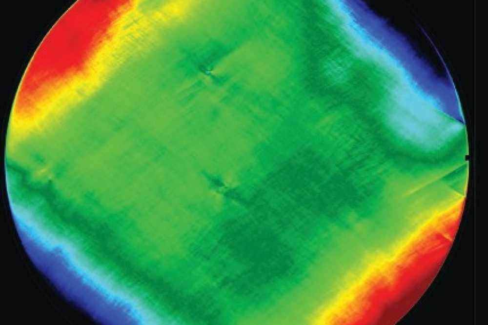
Figure 1. The quality of material can be evaluated by considering values
provided by w-scans, produced by X-ray diffraction. The general trend
is a decreasing value for ∆w with increasing layer thicknesses. Grey
squares and circles refer to other c-GaN layers grown by MOCVD and MBE
on comparable 3C-SiC substrates (left). An atomic force microscopy image
offers insight into surface morphology, uncovering mono-atomic steps
across the smooth surface of c-GaN (right).
Of these two classes of semiconducting materials, the group-III nitrides – they include AlN, GaN, InN and their alloys – are preferred, being viewed as the crucial semiconductor materials for the current and next-generation of optoelectronic technologies. Up until now, all relevant devices made from this material system are based on the thermodynamically stable hexagonal phase.
At the very heart of these III-nitride devices, which emit in the blue and green, are InGaN multilayer structures that incur inherent internal electric fields. This gives rise to the quantum confined Stark effect (QCSE), which result from the interplay of the spontaneous polarisation that arises from the inherent asymmetry of the hexagonal crystal structure, and the piezoelectric polarisation, an undesirable effect of strain in this crystal structure. One culmination of the QCSE, which impedes radiative recombination, is a spatial separation of the electrons and holes in the quantum wells.
These issues are particularly prevalent at longer wavelengths. To propel emission from the blue to the green and beyond, the indium content in the InGaN quantum wells has to increase. But this induces even more strain in the active region, enhancing the QCSE and driving down the radiative recombination rate.

Figure 2. TX-ray diffraction of the asymmetric (113) reflection of c-GaN. The reciprocal space map reveals a pure cubic phase and a single, partially strained c-In0.47Ga0.53N layer.
Another side effect of the increase in indium richness in the wells is a screening of the QCSE under high injection conditions. A decrease in colour stability results – although this can be turned into an advantage, if there is a need for colour tuning.
For phosphide LEDs there is a different set of issues at play. When miniaturising these devices, surface recombination drags down efficiency, due to an increased surface-to-volume ratio. While it might be possible to address this concern, there is also a more fundamental one that cannot be overcome. With this material system, as the composition is adjusted to shift the emission towards the green, the bandgap switches from direct to indirect. This causes efficiency to plummet, and prevents the use of phosphides for the manufacture of blue and green LEDs.
The cubic advantage
Intriguingly, group III-nitrides can also crystallise in the metastable cubic structure. This form promises several advantages, stemming from a polarisation-free material system that is inherent, thanks to cubic crystal symmetry. The most prominent merit of such a structure is that it is free from the QCSE, equipping LEDs with superior colour stability at higher injection currents. Additional advantages of c-GaN over its hexagonal counterpart include a high carrier mobility, a high p-type conductivity and a high electron drift velocity.
As well as all these attributes, c-GaN has a bandgap of 3.2 eV. That’s 0.2 eV lower than h-GaN, reducing the necessary indium content by about 10 percent for targeting a particular emission wavelength in the red.
Due to the combination of an absence of the QCSE and a lower bandgap, cubic nitrides promise to provide a material platform for LEDs spanning the entire visible range. The opportunity to produce powerful blue, green, and red emitters from this material system is incredibly attractive for cost-efficient integration schemes, in particular, once ported onto 300 mm silicon wafer technology.

Figure 3. Normalised low-temperature photoluminescence spectra of c-InxGa1-xN
with values for x ranging from 0.1 to 0.5. The spectrally integrated
intensity is shown as dots (left). Peak emission energy versus indium
content, where black squares denote data points of this work and red
symbols refer to the emission energies of bulk c-InxGa1-xN (right).
Another niche for MBE?
Today, virtually all nitride devices on the market are produced by MOCVD. While this may be desirable for commercial reasons, MBE has advantages for the metastable cubic phase: the extreme nonequilibrium growth conditions associated with this form of epitaxy include a larger temperature window. In particular, the potential for growth at lower temperatures may be superior for future CMOS-compatibility. Additional advantages of MBE include the virtual elimination of hexagonal inclusions, and the ability to incorporate more indium into the epilayer; the latter helps to shift emission to longer wavelengths.
Together with our partners from Phillips-University Marburg, our team at Justus-Liebig University Giessen has produced cubic III-nitride structures on 3C-SiC/silicon(001) substrates using plasma-assisted MBE. This platform for the growth of c-GaN has a lattice mismatch of 3.4 percent, currently the lowest of all commercially available substrates. The samples we have produced clearly exhibit superiority structural qualities compared with other growth techniques (see Figure 1) and substrates.
To assess the crystal quality of our material, we use X-ray diffraction rocking curves (w-scans), considering values for the full-width at half-maximum. This metric provides a direct insight into the density of structural defects. What’s more, this approach is extremely robust, providing reproducible measurements that are commonly reported in most publications featuring epitaxial growth.
Using this methodology, we have benchmarked our material against that of values in the literature for other cubic GaN layers grown on comparable 3C-SiC/silicon substrates. This exercise showcases the superiority of our process. It should be noted that there is a trend of a decrease in the width of the diffraction peak as the thickness of the epilayer increases. In general, this phenomenon is associated with the coalescence of threading dislocations.
Another important characteristic associated with epitaxial growth is the roughness of the film – it must be minimised to ensure high-quality growth of multi-layered heterostructures. Following optimisation, we are able to produce c-GaN layers that feature very smooth surfaces. When we scrutinise the surfaces of our epistructures with atomic force microscopy, we identify atomic steps (see the right-hand panel of Figure 1). We view this observation as a hallmark of the great quality of our c-GaN as a template for subsequent growth of c-InGaN.

Figure 4. Characteristic energy-dispersive X-ray spectrometry (left) and
scanning transmission electron microscopy (right) of a c-In0.47Ga0.53N
sample. The cross section of energy-dispersive X-ray spectrometry shows
a very homogeneous distribution of the elements gallium (red) and
indium (green). This is a noteworthy finding, as a sample with this
indium content lies at the heart of the often literature-perceived
miscibility gap.
Spanning the spectrum
It is challenging to grow metastable cubic InxGa1-xN with good epitaxial quality, due primarily to differences in lattice constant, and the need for a significant difference in growth temperatures for the two binary compounds. Consequently, there are few reports of InxGa1-xN alloys with an indium content of more than 0.3. Note that our search in the literature also uncovered publications that report spinodal decomposition for InGaN with intermediate indium contents.
Against this backdrop we have had considerable success, demonstrating the growth of metastable, phase-pure cubic InGaN layers across the entire composition range. By being able to produce all compositions of InGaN, from InN through to GaN, we are able to continuously tune the emission energy from 0.7 eV to 3.2 eV. To span this domain, we carefully adjust the relevant growth parameters while maintaining successful strain management.
Following the growth of our range of InGaN thin-film samples, we evaluated their composition, phase purity, and degree of strain relaxation with asymmetric reciprocal space maps. Ultimately, these maps uncover the relationship between the amount of indium incorporated in an epilayer and its residual strain. The latter strongly influences the alloys’ miscibility and, thus, the impact on the optical properties.
It should be noted that substrate-induced strain leads to slight differences in the in-plane and out-of-plane lattice constants. Our reciprocal space maps allow us to determine all lattice constants and consequently quantify the residual strain of the InxGa1-xN layers. We find that all c-InxGa1-xN layers grown on c-GaN are partially strained. This is a particularly important observation, because theoretical calculations predict enhanced miscibility, due to the suppression of spinodal decomposition in strained layers. We have observed that uniaxial strain is highest for intermediate indium compositions. This strain counteracts spinodal decomposition and is thus responsible for the full miscibility found in our c-InxGa1-xN layers.
We have measured the photoluminescence of our samples at cryogenic temperatures (see Figure 3). Spectra for compositions with an indium content ranging from In0.11Ga0.89N to In0.5Ga0.5N are broad, with a single peak. Notably, the spectrally integrated emission intensity only quenches by a factor of two across the complete visible range – this is much less than that observed for currently established technologies.
As we are able to produce alloys of c-InGaN across the whole composition range, we have the opportunity to span an emission range from below 400 nm to beyond 1.55 µm. All our samples stretching over this domain produce photoluminescence, and we find a bowing of the emission energy with indium content. These results are a rarity, given that reports associated with InGaN with a high indium content are few and far between. In general, either the materials are not realised – potentially due to presumed spinodal decomposition – or reports are limited to structural properties, with no emission data provided.
Confirmation of the high structural quality of our layers comes from transmission electron microscopy. One example of this, shown in Figure 4, is a characteristic image of a c-GaN/c-In0.47Ga0.53N sample. According to energy-dispersive X-ray spectrometry data, also shown in Figure 4, there is no evidence of any spinodal decomposition.
Remaining challenges
Significantly threatening the performance of optoelectronic devices are extended defects, such as stacking faults. That’s a concern for us, as there are numerous stacking faults in our c-InxGa1-xN on c-GaN samples, according to defect-sensitive low-angle annular dark-field scanning transmission electron microscopy.
However, this situation may not be as concerning as it first appears. The majority of stacking faults in our c-InxGa1-xN layer originate in the c-GaN layer, forming at the substrate interfaces during the nucleation of GaN on 3C-SiC. If these faults are not annihilated, they will penetrate the InxGa1-xN/GaN interface and propagate through the entire epitaxial layer. To reduce the number of stacking faults in c-GaN, one can incorporate a thin c-AlN buffer. Its addition drives down the concentration of stacking faults in the c-InxGa1-xN layer.
The progress that we have made provides a solid foundation for further development of cubic nitride technology. While we have made much progress, more is needed, including improvement to material quality. Such efforts must include the development of successful doping strategies and high-quality quantum structures, goals that will demand optimised growth conditions and possibly the use of alternative substrate technologies. The latter may tackle challenges related to anti-phase domains, which originate from the interface between the group IV material and the cubic nitrides.
While microLEDs for AR and MR are showing much promise, they are struggling to make significant breakthroughs. Cubic GaN can be game changer. Its growth is not trivial, but much can be accomplished with MBE.
Main image: Photo credit: Elisa Monte