Cranking up the switching speed with a p-GaN shield

Adding a p-GaN shield to a vertical GaN-on-GaN transistor trims capacitance and enhances high-power, high-speed switching.
BY NAOKI TORII, DAISUKE SHIBATA, MASAHIRO OGAWA, MASAO KAWAGUCHI, HIROYUKI HANDA, NAOHIRO TSURUMI, SATOSHI TAMURA AND YOSHIO OKAYAMA FROM PANASONIC
Sales of power electronics are tipped to soar throughout this decade and beyond. Driving this trend is the increase in production of electric vehicles and the growth of data centres, which have more demanding power requirements due to the uptake of AI.
For every application using power electronics, an increase in their efficiency is beneficial. Gains may include an increase in driving range, a reduction in electricity bills, less heating, and a lower carbon footprint.
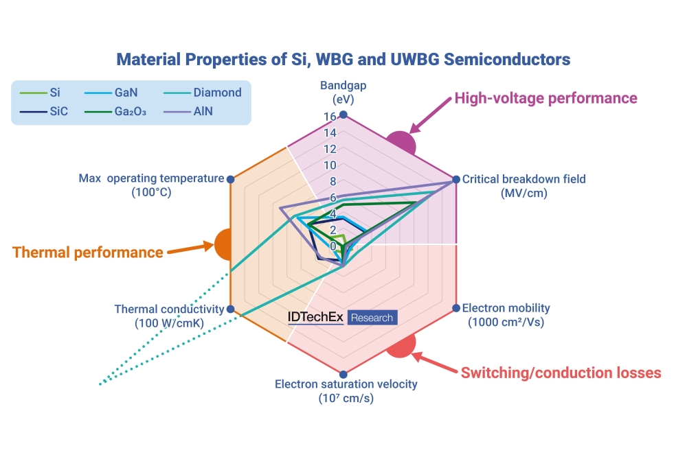
Due to these benefits that result from a superior efficiency, there is an increasing uptake of devices based on wide bandgap semiconductors. So far, those based on SiC have generated the most revenue, with MOSFETs grabbing headlines for winning deployment in electrical vehicles.
However, despite enjoying much success, SiC devices have some significant deficiencies. They included the interface between SiC and SiO2, which is far from perfect.

Figure 1. Panasonic’s vertical JFET features a p-GaN shield structure that enables superior switching, thanks to a reduced reverse-transfer capacitance.
Avoiding these issues is the lateral GaN transistor, which is already netting significant sales by dominating the market for the fast-charging of mobile devices. One of the benefits of this class of device, which can be grown on large-area, low-cost silicon substrates, is that high levels of mobility are realised without doping. Instead, internal polarisation is exploited to produce a two-dimensional electron gas (2DEG).
This lateral device is a significant milestone for the GaN transistor, providing the first ‘killer’ application – premium fast-charging units for the likes of smartphones, tablets and laptops. But going beyond this is far from easy with these lateral devices, because it is very challenging to reach high values for output current and breakdown voltage and thus output power. With this device geometry, critical design considerations for high power are the area of the electrodes, and the spacing between the source and drain on the surface of the device.
Offering a very promising way forward is a new architecture, involving a shift from a lateral to a vertical geometry. With these more compact devices, which a number of teams have been developing from around the world over the last few years, source and drain electrodes are placed on opposite sides of the substrate, enabling design engineers to scale the power of the transistor while not significantly increasing its footprint.
Our company, Panasonic, is one of the trailblazers of the vertical GaN transistor. We have developed a variant that’s a high-power vertical GaN JFET, which we refer to as a VJFET. It’s produced using the re-growth of p-GaN/AlGaN/GaN channels.
For GaN devices to realise their full potential at the system level, where they promise to aid miniaturisation and trim loss, it is essential that they are capable of high-speed switching. Governing this key metric is the reverse-transfer capacitance – also known the capacitance between the gate and the drain – that impacts the mirror period required to charge the capacitance between the gate and drain.

Figure 2. Panasonic’s process for the fabrication of its vertical JFET with a p-GaN shield structure.
Conventional VJFETs are held back by a high reverse-transfer capacitance, associated with opposing placement of gate and drain electrodes. But we have recently addressed this issue with a ground-breaking refinement to the device: the addition of a p-GaN shield on a normally-off GaN VJFET that’s grown on a native substrate (see Figure 1 for details of its structure).
Simulation insights
To evaluate and understand the benefits and implications of this device, we have simulated its performance. This is benchmarked against the conventional VJFET that combines normally-off operation with a low on-resistance, and features a re-grown p-GaN gate/AlGaN/GaN structure formed on a V-groove.
Our novel VJFET has a strategically introduced p-GaN shield over the V-groove that is at the same potential as the source. For this device, the gate is formed on the plane separately from the p-GaN shield structure. This design has a far lower reverse-transfer capacitance than its conventional counterpart, thanks to effective shielding between the gate and drain by the p-GaN well and the p-GaN shield structure.
Simulations of both forms of VJFET show that our refinement to this transistor delivers a substantial reduction in the reverse-transfer capacitance over a wide range of drain-source voltages. Over a range of voltages up to 500 V, our device has a reverse-transfer capacitance that’s well below a picofarad, while its conventional counterpart has a value of many tens of picofarads. These simulations also show that shortening the length between the edge of the p-well and the p-GaN gate enables an additional reduction in the reverse-transfer capacitance.

Figure 3. A scanning electron microscopy image of a p-GaN shield vertical JFET.
Our simulations have also revealed that with our VJFET with a p-GaN shield, the thickness of the AlGaN barrier has a strong influence over normally-off operation and a low on-state resistance. By modelling this device, we have determined the profile of the conduction band and the density of the 2DEG, for a gate-source voltage of 0 V. This work shows that in the gate region complete depletion is realised with a 20 nm-thick Al0.2Ga0.8N barrier layer. Meanwhile, in the slanted region, an Al0.2Ga0.8N barrier that’s 80 nm-thick enables the formation of a high-density 2DEG and a low channel resistance.
Further findings from our simulations reveal that as well as slashing the reverse-transfer capacitance, our V-shaped p-GaN shield structure in the V-groove suppresses the off-state leakage current by relaxing the electric field at the p-GaN well’s edge, where there is damage caused by the dry etching process. This work has also determined that increasing the distance between the bottom of the p-GaN well and the bottom of the p-GaN shield reduces the electric field strength at the edge of the p-GaN well, thanks to a relaxing of the electric field by the p-GaN shield structure. There is a price to pay for this benefit, however: as the distance between the bottom of the p-GaN well and the bottom of the p-GaN shield extends, there is an increase in the electric field strength at the bottom of the p-GaN shield.
Based on these findings, we have concluded that experimental investigations are needed to optimise the distance between the bottom of the p-GaN well and the bottom of the p-GaN shield while realising a low off-state leakage current.

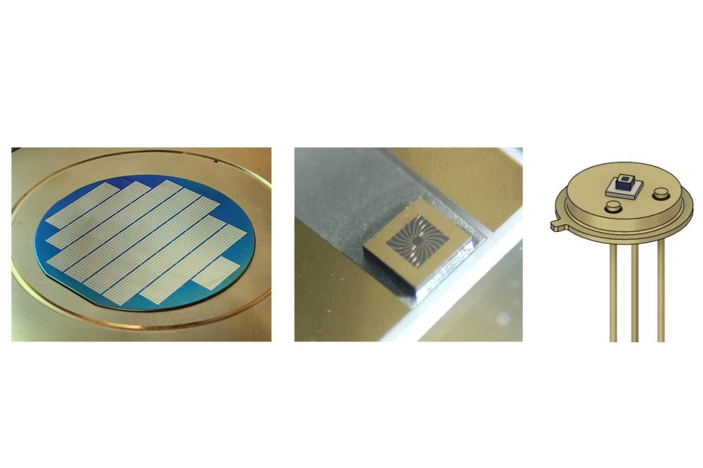
Figure 4. Designed for high-current operation, this p-GaN shield vertical JFET has a chip size of 2.9 mm by 2.6 mm.
Device fabrication…
Fabricating our novel VJFETs began by loading bulk GaN substrates into an MOCVD reactor and depositing a 7 µm-thick silicon-doped GaN drift layer with a carrier concentration of 1.3 x 1016 cm-3, followed by a magnesium-doped p-GaN well with a carrier concentration of more than 1.0 x 1019 cm-3. With this heterostructure, the blocking voltage should exceed 900 V.
The next steps in the fabrication process involved etching V-shaped grooves in the epiwafer with an inductively coupled plasma, and re-growth of Al0.2Ga0.8N and GaN. We varied the thickness of the Al0.2Ga0.8N barrier layer from 50 nm to 80 nm, and employed a thickness for this ternary of 20 nm under the gate, realised by partial removal with inductively coupled plasma etching.
To complete the fabrication of our VJFETs, we added a p-GaN epilayer, and selectively etched this to form the gate and p-shield structure. We then applied a selective etch to the Al0.2Ga0.8N/GaN/p-GaN well to form the source electrode. The final device features a Ti/Al source electrode, a Pd/Au gate electrode, a p-GaN shield electrode, and a Ti/Al/Ti/Pt/Au electrode on the backside of the GaN substrate (see Figure 2 for an overview of the fabrication process, and Figure 3 for a scanning electron microscopy image of our device).

Figure 5. On-state (left) and off-state (right) DC output characteristics of the p-GaN shield vertical JFET.
… and characterisation
Electrical measurements of our transistors, which have an active area of 0.002 mm2, reveal a threshold voltage of 1.5 V. The on-state resistance decreases with the thickness of the barrier layer, and for an 80 nm thickness, the product of on-resistance and area is 1.23 mΩ cm2. Plots of off-state leakage current at a range of drain-source voltages show that the leakage is far less when the distance between the bottom of the p-GaN well and the bottom of the p-GaN shield is 200 nm, rather than 0 nm or 400 nm. For the 200 nm distance, the drain-source voltage has little impact on leakage current, which is around tens of microamps per square centimetre.

Figure 6. The p-GaN shield enables a substantial reduction in reverse-transfer capacitance.
We have also evaluated a 2.9 mm by 2.6 mm p-shield VJFET designed for high-current operation (see Figure 4). This device has a maximum drain current of 57 A, an on-state resistance of 58.6 mΩ, and a breakdown voltage of 972 V (see Figure 5). Encouragingly, at a drain-source voltage of 500 V, the reverse transfer capacitance is just 2.92 pF – that’s less than one-eighth of the value for its conventional counterpart (see Figure 6). In addition, the input capacitance is lower, thanks to the reduced gate area.
A key figure-of-merit for our p-shield VFJET is the product of its on-resistance and its reverse-transfer capacitance. This figure is just 171 mΩ pF, less than that for commercially available SiC MOSFETs (see Figure 7).

Figure 7. Benchmarking the Panasonic p-GaN shield vertical JFET against its conventional counterpart and 650 V SiC MOSFETs, using figures provided by data sheets.
Using an inductive load, we have investigated the switching performance of our p-shield VJFETs at 400 V and 20 A. Values for turn-on are 14.3 V ns-1 and 76.7 V ns-1 for our conventional and p-shield VJFETs, respectively. The turn-on loss is reduced by 75 percent compared with that for a conventional device.
Based on a wide portfolio of results, we can conclude that our novel VJFETs are promising candidates for serving in applications requiring high powers and high speeds.
•This work was partly supported by ‘Project for Acceleration of Social Implementation and Dissemination of Components and Materials for Realizing Innovative CO2 Emission Reduction’ of the Ministry of Environment of Japan.