New directions for GaN electronics

Advances in epitaxy and processing are opening up new opportunities for GaN in handsets, computation, and the delivery of RF signals in the X-band
BY RICHARD STEVENSON, EDITOR, CS MAGAZINE
GaN is, without doubt, the most important and pervasive material within the family of compound semiconductors. It’s initially enjoyed tremendous success within the optoelectronics domain, where it’s been used for several decades to produce countless LEDs, as well as blue and green lasers that are deployed for a variety of tasks, including material processing and colour projection.
While some may argue that the best days of GaN optoelectronics are now behind us, the same cannot be said for the electronics sector. Here GaN is increasingly employed for RF power amplification and fast-charging, with sales sure to increase with improved performance – and there are also lucrative opportunities in handsets and computation.
Key to fulfilling all these promises are technological breakthroughs, which may take the form of improvements in device design or processing. Many advances on these fronts are reported at global conferences, and at the most recent International Electron Devices Meeting held in early December in San Franscico three significant milestones were unveiled: the first integration of a GaN low-voltage power amplifier into a handset, where a three-stage III-N MMIC provided an efficiency of over 50 percent; the development of a GaN chiplet technology based on 300 mm GaN-on-silicon that has much appeal for high-performance, high-density efficient power and high-speed/RF electronics; and the fabrication of an X-band GaN-on-SiC-based HEMT that delivers a substantial hike in power density, realising 41 W mm-1.
Handsets: From GaAs to GaN?
Since the mass adoption of the mobile phone at the turn of the millennium, the critical task of RF amplification has been performed with a GaAs-based device, typically a HBT. One of its strengths is that it’s well-suited to being driven by a battery, which provides just a few volts.
Offering an attractive alternative on several fronts is the GaN-on-silicon PA. This technology delivers a superior power performance from a smaller form factor, a key advantage, given the limited space in smartphones. What’s more, GaN-on-silicon HEMTs have the potential to be integrated with on-chip power supplies, and can be manufactured in high volume in silicon lines, ensuring cost-competitive chip production.
However, for deployment in handsets, the GaN-based PA has an Achilles heel – its high operating voltage, with devices typically driven at 28 V. But there is no longer a need to target a reduction to just a few volts to develop a handset-friendly solution, thanks to the introduction of higher supply voltages of up to 10 V, realised with the introduction of advanced power management ICs.
Taking advantage of this and delivering a step-change in the performance of PAs that can serve in handsets is a collaboration led by Dynax Semiconductor and involving engineers at Xiaomi Communications and The Hong Kong University of Science and Technology.
Speaking on behalf of this partnership at IEDM, Haochen Zhang from Dynax highlighted a HEMT efficiency of over 80 percent at a drain voltage below 10 V, and a three-stage GaN MMIC evaluated in the main board of a smartphone with a power-added efficiency of more than 50 percent.
“We believe that this marks the dawn of a wireless communication era defined by gallium-nitride-based radio-frequency technologies,” remarked Zhang.
Dynax, which has constructed an advanced GaN manufacturing centre that includes a 4,500 m2 cleanroom, has devoted many years to pursuing the deployment of GaN in handsets. Efforts have been supported by an R&D team with over 150 staff that has helped to file over 500 patent applications, both domestically and internationally.
Zhang explained that one of the three key challenges the collaboration faced in developing a GaN PA technology for mobile phones was to ensure that the knee-voltage is as small as possible. “Secondly, gallium nitride devices suffer from gain soft-compression, which undermines linearity. Thirdly, unlike gallium arsenide HBTs, which are voltage-driven D-mode devices and work comfortably at 4.5 volts, gallium nitride devices are voltage-driven D-mode devices with a relatively high operating drain voltage.”
To address the latter concern, Zhang and co-workers introduced a power-management IC, and considered the voltage supply to both the gate and the drain.

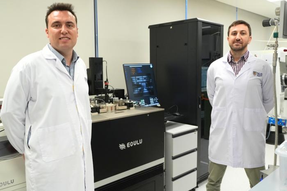
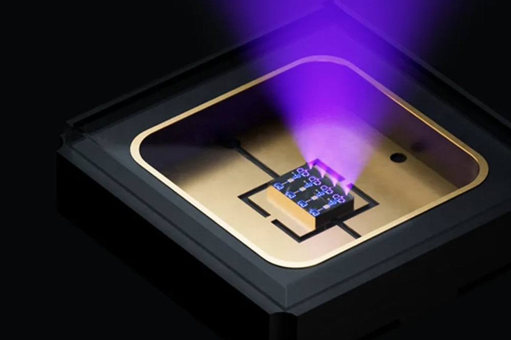
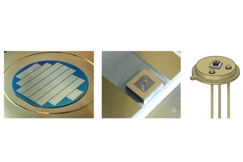
Figure 1. Engineers at Dynax Semiconductor, Xiaomi Communications and The Hong Kong University of Science and Technology have developed a GaN HEMT for providing RF amplification in handsets.
Fabrication of the collaboration’s devices (see Figure 1) began by loading high-resistivity silicon substrates into an MOCVD reactor, applying an in-situ substrate treatment, and adding an AlN nucleation layer with an optimised thermal budget to regulate the distribution of impurity atoms at the AlN-silicon interface. This approach is claimed to reduce aluminium diffusion into the silicon substrate and suppress the formation of a parasitic channel in silicon, which would lead to an RF loss associated with the substrate.
“The substrate loss and interface loss is optimised, to be around 0.2 dB at 10 gigahertz, which is a level comparable to gallium-nitride-on-silicon-carbide devices,” remarked Zhang.

Figure 2. Substrate loss for III-N-on-silicon heterostructures is reduced with an AlN nucleation layer that has an optimised thermal budget and regulates the distribution of impurity atoms at the AlN-silicon interface.
Using these epiwafers, the team deposited a hard mask for re-growth of heavily doped GaN. Dry etching removed the SiOx/SiNx hard mask prior to GaN re-growth, involving a pre-dose of indium atoms that acted as a surfactant, improving interface morphology and promoting doping efficiency through the suppression of silicon self-compensation. Fabrication of the HEMTs was completed with hard mask removal, surface passivation through low-pressure CVD of SiNx, and the addition of source and drain electrodes and a T-shaped gate. Resulting devices have a contact resistance of 0.09 Ω mm and a sheet resistance 251 Ω/sq.
Measurements of the DC characteristics of these devices – which have a gate length of 0.25 µm, and gate-to-source and gate-to-drain distances of 0.4 µm and 0.8 µm, respectively – determined an on-resistance of 0.76 W mm-1, a knee voltage of 1.6 V, and a saturated drain-source current of 1.5 A mm-1. It is said that these impressive figures provide the foundation for the high performance of the GaN HEMTs.
The breakdown voltage for these transistors is 98 V, a value claimed to fully guarantee device performance, ruggedness and reliability.
Small-signal characteristics at a drain-source voltage of 5 V revealed a peak cut-off frequency (fT) of 31.2 GHz and a maximum oscillation frequency (fmax) of 66.2 GHz, and large-signal power sweeps determined a power-added efficiency of 84.2 percent and a maximum output power of 2.84 W mm-1.
Zhang pointed out that even higher output powers have been realised by other teams, using devices with an InAlN barrier layer. “However, the reliability of such indium-incorporated devices remains an issue.”
To determine the reliability of their devices, Zhang and co-workers subjected 15 devices to high-temperature reverse bias tests (HTRB) and high-temperature operating lifetime (HTOL) tests.
“After the HTRB and HTOL stress, the devices show negligible performance degradation,” said Zhang. For example, the change in output power is below 0.1 dB.
The engineers also determined a mean-time-to-failure of 2,500 years at a junction temperature of 225 °C.
These GaN HEMTs provided the key building block for a three-stage PA MMIC that features a shunt power structure with high-pass and low-pass networks to increase bandwidth and linearity.
Zhang told delegates that to optimise linearity, it is critical to consider the inter-stage matching network between the driver PA and the final-stage PA. And he revealed: “To counteract gain compression, the gain curve of the driver stage was deliberately designed to expand at power saturation, and thereby enhance gain flatness over the entire bandwidth.”
Measurements of this MMIC under modulated signals at 2 GHz revealed a gain of 39.3 dB and a power-added efficiency of 60.1 percent. Benchmarking against GaAs HBTs, using values in publications and for a commercial product (see Table 1), led Zhang to claim: “This work demonstrates significantly higher output powers, due to a higher supply voltage, and especially optimised device fabrication and epi processes.”

Table 1. A comparison of the performance of the III-N-on-silicon low-voltage MMIC produced by engineers at Dynax Semiconductor, Xiaomi Communications and The Hong Kong University of Science and Technology: [1] W. Y. Refai et al. IEEE Trans. Microw. Theory Tech. 68 3519 (2020); a commercial product, the RF7205;[2] M. Liu, et al., IEEE Microw. Wireless Tech. Lett. 33 1305 (2023).
The team’s three-stage MMIC has been evaluated on a smartphone mainboard using a radio communication tester, connected to the antenna connector by a coaxial cable. The phone battery powers the system, and is paired with an external power management IC that integrates logic control, boost conversion and negative-voltage generation for MMIC biasing. Thanks to the introduction of the power management IC, the smartphone battery voltage increases from 3.8 V to 10 V, with this voltage applied to the drain bias.
Using π/4-QPSK modulation with a 20 percent duty cycle and a frequency of 2 GHz, the power amplifier produced an output power of 38 dB at a power-added efficiency of 51.4 percent.
“In future work further device linearity is required, especially for high-order modulation,” remarked Zhang, who commented that there is also the opportunity to shrink dimensions, via system-in-package designs, such as those based on flip-chip bonding.

GaN chiplets
Figure 3. As demand increases for higher
power density and efficiency increases, there will be an evolution in GaN
point-of-load power solutions from discrete motherboard voltage-regulators
(MBVR) to GaN vertical power, and then to chiplet integration with GaN power
chiplets.
In computing, it is expected that over time discrete silicon components powering motherboard voltage regulators will be replaced with GaN technologies – initially GaN discrete modules; and then approaches where GaN power modules are still on the board, but situated directly below the compute package; and finally, a transition to chiplet integration, with GaN power chips integrated with other die in the same compute complex (see Figure 3). For the latter, options include what is described as Foveros integration and next-generation 3D chiplet integration (see Figure 4).
 Figure 4. Examples of chiplet integration
with GaN power chiplets: (a) Foveros integration, (b) next-generation 3D
chiplet integration.
Figure 4. Examples of chiplet integration
with GaN power chiplets: (a) Foveros integration, (b) next-generation 3D
chiplet integration.
Efforts to develop these new technologies, needed to address demands for higher power densities, superior efficiencies and tighter integration, are underway at Intel – and at the recent IEDM meeting Han Wui Then detailed this company’s development of GaN chiplets, as well as the industry’s first library of fully integrated on-die CMOS digital circuits, produced using a monolithically integrated GaN n-type MOSHEMT and silicon PMOS process.
According to Then, as there is little room in any direction to house the chiplets in the complex, it’s critical that the GaN transistor technology has a high density, a high performance, and is capable of delivering current densities of at least 10 A mm-2.
In addition to these requirements, the GaN chiplets need to be ultra-thin – their thickness must be well below 50 µm – as this will enable short (low aspect-ratio), low-resistance through-silicon vias that ensure low resistive losses and acceptable thermal dissipation.
While ticking these boxes, it’s important to note that there is no room in the complex to accommodate more chiplets, such as CMOS companion dies.
“It is crucial that the gallium nitride chiplets are as complete as possible, with the required functionalities, such as CMOS controllers, low-leakage drivers, PMOS current mirrors, telemetry circuit tees, etcetera,” remarked Then, who added that functionalities, such as integrated CMOS drivers and date time controllers, are essential for achieving optimal efficiencies and fast-switching to minimise passives.
“To this end, we demonstrate, for the first time, a library of fully functional integrated on-die CMOS digital circuits – from inverters, logic gates, multiplexers and flip-flops to ring oscillators – all implemented with a monolithically integrated gallium nitride and silicon PMOS process that’s achieved by layer transfer and designed using a process design kit.”
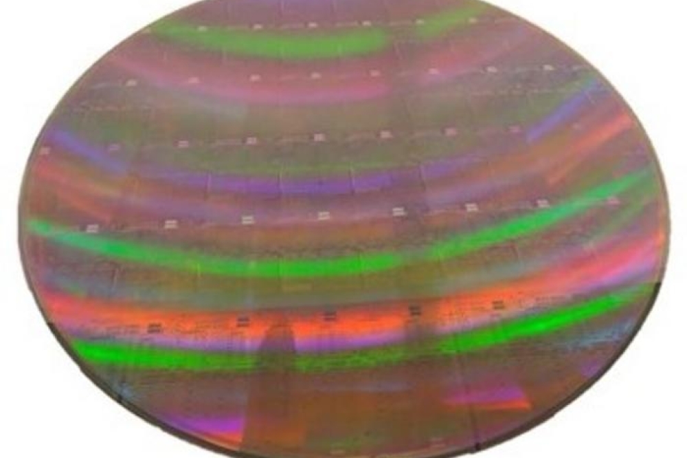
Fabrication of the chiplets involves what’s described as a ‘stealth dicing before grinding’ process that produces a thinned, singulated 300 mm GaN-on-silicon wafer. Following this process, the underlying silicon substrate is just 19 µm thick, leading Then and co-workers to claim that they have produced the industry’s thinnest fully processed 300 mm GaN wafer.
According to Then, characterisation of GaN transistors with a 30 nm gate length has determined: an excellent on-resistance; a low gate leakage, below 3 pA µm-1; a breakdown voltage of up to 80 V; and values for fT and fmax of 212 GHz and 304 GHz, respectively. For gate lengths up to 130 nm, fmax remains above 200 GHz.
It’s claimed that this RF data bodes well for RF and high-speed applications, such as photonics. According to the research team behind this work, their GaN chiplet technology could have potential use in these applications.
Then and co-workers have undertaken an extensive reliability study of their GaN MOSHEMTs, with investigations considering time-dependent dielectric breakdown, positive-bias temperature instability, HTRB and hot-carrier injection.
It’s claimed that these studies demonstrate promising results towards meeting the reliability metrics for 300 nm GaN MOSHEMT technology.
Hiking power in the X-band
GaN HEMTs operating in the RF domain are widely deployed in satellite communication, radar and 5G base stations. They are valued in all these applications for their high-power density, peaking at around 31-33 W mm-1.
While this figure is far better than that for RF transistors produced with traditional III-V technologies, it has not improved significantly for around two decades – until now, thanks to work by a Chinese partnership that’s led by engineers at Xidian University, and also involves researchers at Dynax Semiconductor, Chengdu Aerospace Bomu Electronic Science and Technology Company and Wuhan University.
Speaking on behalf of this partnership at IEDM, Hong Zhou from Xidian University remarked: “The achieved device performance sets several new records for gallium nitride RF power transistors.” They include a record maximum output power density of 41 W mm-1 and a value for the product of fT and breakdown voltage of 31 THz V (see Figure 5 for device and processing details).

Figure 5. A passivated AlGaN/GaN/AlN RF power HEMT on a SiC substrate produced by a partnership between Xidian University, Dynax Semiconductor, Chengdu Aerospace Bomu Electronic Science and Technology Company and Wuhan University. Key elements of this work include a film-like AlN buffer and a thin GaN channel.
According to Zhou, the hike in performance comes from optimisation of the heterostructure, including an abrupt interface between AlN and SiC.
Zhou and co-workers attribute the lack in progress prior to their work to issues associated with the growth of GaN-based epistructures on foreign substrates, typically SiC. The island-like AlN nucleation layer that’s often employed creates a high thermal boundary resistance between AlN and SiC; and another common downside is a GaN buffer with a thickness of a micron or more, which provides a much-needed reduction in dislocation density, at the expense of an additional compromise in thermal conductivity.

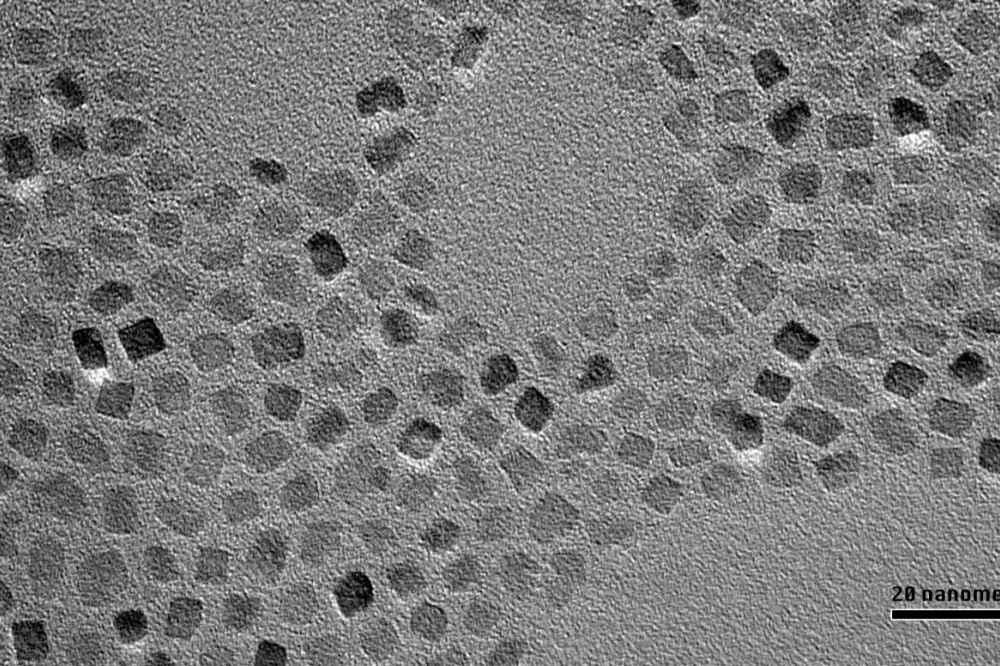
Figure 6. High-resolution transmission electron microscopy image of AlN/SiC interfaces with different growth conditions reveal the benefits of a relatively low growth rate and V-III ratio. (a) V-III ratio of 2100 and growth rate of 2.5 nm min-1, (b) V-III ratio of 800 and growth rate of 7.3 nm min-1, and (c) V-III ratio of 800 and growth rate of 2.5 nm min-1. With an optimised V-III ratio of 800 and a growth rate of 2.5 nm min-1, an atomically abrupt interface between a high-quality AlN buffer and SiC substrate can be formed.
These issues are addressed with a film-like AlN buffer, providing an abrupt AlN/SiC interface that reduces the thermal boundary resistance and the dislocation density.
Success has come from the growth of an AlN buffer layer, using the following conditions to enhance aluminium adatom surface migration: a V-III ratio of just 800; a growth temperature of 1300 °C; and a growth rate of only 2.5 nm min-1 (see Figure 5). On this buffer, just 190 nm-thick, the team added a 210 nm-thick GaN channel that has a defect density of just 1.67 x 108 cm-2, according to cathodoluminescence mapping.
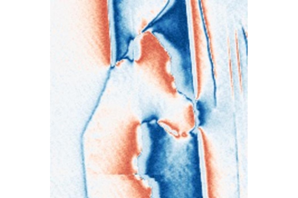
The superior heat dissipation of the thinner structure is highlighted in laser-based transient thermoreflectance measurements. This technique shows that for a conventional power device with an AlN nucleation-island and a 1.2 µm-thick GaN buffer layer, device temperature increased by 98 K when operating at 13 W mm-1. In comparison, there is an increase in temperature of just 47 K for the thinner device, when operating at the significantly higher power density of 24 W mm-1.
Additional measurements have determined a sub-threshold swing of 77 mV dec-1 and an on-off ratio of 109, results indicative of a high-quality interface. For a device with a gate-to-drain distance of 1.2 µm, the maximum blocking voltage is 161 V – that’s claimed to be higher than that in traditional GaN RF devices, an increase attributed to the effectiveness of the ultra-wide bandgap AlN barrier in boosting the blocking field.
Zhou and co-workers are also encouraged by the results of gate- and drain-lag measurements, which show a dispersion of less than 8 percent and validate the suppression of self-heating and current collapse effects.
Values for fT and fmax are 72 GHz and 134 GHz, respectively, for their novel HEMT with a 230 nm gate length and a drain-to-source spacing of 2.2 µm. Increasing this spacing to 8.6 µm produced a fall in fT and fmax to 56 GHz and 104 GHz, respectively.
Using a device with a drain-to-source spacing of 5.6 µm and a 230 nm gate length, at a source-to-drain voltage of 90 V and a gate width equal to 240 µm (2 x 120 µm), a 10 GHz input signal with a pulse width of 10 µs and a duty cycle of 10 percent produced an output power of 31 W mm-1 at a power-added efficiency of 51 percent. Increasing the drain-source voltage to 115 V, and moving to 5 µs pulses and a duty cycle of 0.5 percent, increased the output power to a record 41 W mm-1 without reducing the power-added efficiency (see Figure 7).

Figure 7. Peak power-added efficiency (PAE) versus drain-source voltage VDS at two pulse conditions: a pulse width of 10 µs, duty cycle of 10 percent and VDS of 90 V; and a pulse width of 5 µs, a duty cycle of 0.5 percent and VDS of 115 V. A smaller duty cycle at the higher VDS is used to protect the RF probe tips, since each measurement lasts for more than 10 minutes with maximum output power of 40 dBm.
This breakthrough, and those related to GaN chiplets and GaN HEMTs for handset PAs, highlight that while much has already been accomplished with this nitride, there’s more to come.