Technical Insight
Slashing LED chip costs with large-scale silicon
By far the best way to slash the cost of LEDs so that this form of lighting can take over is to grow the device structures on 200 mm silicon. On this platform, the big challenge is to address the thermal and lattice mismatches that can introduce distortions and imperfections in the GaN-on-silicon epiwafers. The good news is that it is possible to form high-quality, device-grade epilayers that are free from a low-temperature AlN layer and SiN interlayers with in-situ monitoring and growth optimisation, says Sudhiranjan Tripathy from IMRE, Singapore.
When one of your light bulbs fails and you head down to your local hardware store to pick up another, you may be faced with a greater choice than ever before. If your government is yet to ban the incandescent bulb, you can pick up a pack of these, which deliver great colour quality but are incredibly inefficient. Next to these you’ll probably spot a range of compact fluorescents, which offer far better efficiency and last much longer, but may not be dimmable and will require careful disposal, due to the mercury they contain. And last but by no means least, you could find a new type of product on the shelves – the LED light bulb. It promises a lifetime of up to 50,000 hours, which is far longer than its rivals; it has an efficiency that exceeds the compact fluorescent; and its compatible with your dimmer switch. But it has an eye-watering price tag – expect to pay around $20 or more for a 60 W equivalent.
The primary culprit for this off-putting price tag is the high cost of the battalion of blue emitting, GaN-based LED chips inside the bulb, which excite a yellow-emitting phosphor to create white light via colour mixing. To slash the cost of these GaN chips and make solid-state lighting more compelling, several groups of researchers around the world are developing devices built on large silicon substrates. Switching to this platform will trim production costs on two fronts: The sapphire and SiC substrates that are widely used today are relatively expensive, and 200 mm silicon-based wafers can be processed cheaply in under-utilized 200 mm foundries dotted around the globe.
Efforts to unlock the promise of GaN-on-silicon LEDs are on going at several chipmakers, including Osram, Bridgelux-Toshiba and Samsung. Many of the researchers at these firms are trying to improve the epitaxial quality on large area silicon, because this is the biggest barrier to device commercialisation. It is essential to have an exceptional AlN nucleation layer and excellent intermediate buffers for the growth of high-quality InGaN/GaN multi-quantum wells (MQWs) on silicon. On top of this, a high level of homogeneity is required in the active layers to ensure good binning data.
At the Institute of Materials Research and Engineering, A*STAR (Agency for Science, Technology, and Research), Singapore, we have been focusing on these issues and have had noteworthy success. We have grown and characterized GaN-based blue LED structures on 200 mm diameter (111)-oriented silicon substrates, and followed this with an in-depth characterization study of LED epilayers by high-resolution X-ray diffraction (HRXRD) and scanning transmission electron microscopy (STEM). In addition, we have produced prototype LED chips with impressive light emission characteristics. Bright blue emission from our chips that are formed on 200 mm silicon underlines the great potential of this GaN-on-silicon technology.
Managing the strain
Producing high-quality nitride films on 200 mm silicon is challenging, because significant differences in the lattice constants and thermal expansion coefficients of GaN and silicon induce a high threading dislocation density in the epilayer. These imperfections drive down internal quantum efficiency, but they can be quashed with strain-management technologies that improve the homogeneity of the active layer emission efficiency.
The best route to relieving the stress in epilayers and realizing crack-free GaN-based heterostructures is to use a carefully selected combination of a buffer and interlayers. For example, a low-temperature AlN nucleation layer, graded AlGaN buffers and Al(Ga)N/GaN superlattices.
One of the consequences of stress is that it causes wafer bow, which must be less than 50 µm to allow the material to be processed in 200 mm foundries that were originally built for CMOS technologies. To meet this requirement, the thickness of the buffer and the intermediate layers should be adjusted while monitoring, in-situ, wafer curvature and reflectance. In order to realize efficient LEDs, the device structure grown on top of this must include InGaN/GaN multi-quantum wells with a high degree of uniformity and sharp interfaces.
We have been working towards all of these goals by developing GaN–on-silicon growth processes in a refurbished Aixtron 19 × 2-inch closed coupled showerhead MOCVD reactor. This tool, which is capable of deposition on a single 150 mm or 200 mm substrate (see Figure 1), is equipped with the latest in-situ reflectance and curvature monitoring tool, a LayTec Epicurve TripleTT interface.


Engineers at IMRE have carried out the development of GaN-on-silicon epitaxial wafers using a modified CCS reactor. (a) The Aixtron MOCVD being used for the development of GaN-on-silicon product at IMRE-Singapore. (b) The usage of the reactor for conventional GaN-on-sapphire 19 × 2-inch mode epitaxy. (c) The same chamber with a 200 mm, deep-pocket susceptor for GaN-on-silicon epitaxy. (d) Images of 150 mm diameter GaN-on-silicon epiwafers, which are also developed at IMRE using the same reactor.
In our opinion, in-situ control can significantly improve the quality of multilayer devices, such as an LED. We have found that the EpiCurve TT system, which provides simultaneous curvature, temperature and reflectance measurements, is a great tool that is capable of working with the narrow viewport geometries that must be used for process optimization near the reactor centre – this is the case for single wafer epitaxy. The three EpiTT sensor heads (see Figure 2a) provide simultaneous detection at three reflectance wavelengths: 950 nm for emissivity-corrected pyrometry; 633 nm for thick layers, such as GaN buffers; and 405 nm for thin layers, such as InGaN/GaN MQWs (see Figure 3).


In-situ growth monitoring has been carried with a LayTec tool that comprises three EpiTT sensors for reflectance and curvature measurements mounted on top of the showerhead. The epitaxy development of GaN-on-silicon is complemented by the 200 mm HRXRD mapping tool for fast reciprocal space mapping and X-ray reflectivity analysis for LED and power electronics projects at A*STAR. Epiwafers with a thin GaN layer on silicon have a symmetrical growth profile.
Our epitaxial process development has been carried out with on-oriented silicon (111) substrates that are loaded directly inside the chamber without any chemical treatment. These substrates are either 1.5 mm or 1.0 mm thick, and they sit in specially designed deep-pocket susceptors. Prior to growth, a high temperature bake-out process cleans the reactor chamber, before the substrate is loaded on the wafer carrier and heated to 950-980 °C under hydrogen gas for several minutes. This removes the native oxide from the silicon surface.
Growth of the LED epiwafers begins with deposition of a thin AlN seed, and then the reactor temperature is ramped up for the growth of a thicker AlN layer – this is more than 600 nm thick in the case of 1.5 mm-thick silicon substrates. Thick, step-graded AlxGa1-xN intermediate buffer layers are interlaced to reduce strain, before a 1.0 µm-thick undoped GaN layer is added on top of this structure, followed by an n-type GaN layer with a silicon doping concentration of 5 × 18 cm-3, an InGaN/GaN MQW active region and p-type, magnesium-doped GaN cap.
Deposition of this structure – typically eight blue-emitting quantum wells and a 150 nm-thick p-type GaN capping layer that is activated at the end of the growth process – shows that it is possible to carry out uninterrupted growth of an LED stack that is free from any interlayer between AlGaN and the top MQWs layers. This avoids the use of a lower-temperature AlN layer, which aids strain management but has its downsides: A longer total deposition time; and a shortening of the lifetime of the heater, which is ramped up and down in temperature more often, and is used in longer growth runs. The cost of these LED epiwafer growth processes are minimised when nucleation, buffer and all interlayer growth take place as fast as possible and yield material with good crystalline quality. Do this, and epiwafers costs are comparable to those associated with production on sapphire. Ideally, the GaN layers on silicon are as thin as those on sapphire, to reduce costs, while the levels of defect density are similar to the incumbent epiwafers.

(a) Reflectance profiles of epilayers measured by LayTec probing tool, which features EpiTT sensors for three wavelength reflectance measurements.
It is crucial to optimise the starting growth conditions for the AlN nucleation layer – these vary with the diameter and thickness of the substrate. When we moved from smaller sizes of silicon substrate to those with a 200 mm diameter, we found that the AlN layer must be thicker. To obtain high crystal quality AlN at a high growth temperature, we adjusted the three zone heater settings in the reactor. The primary purpose of this AlN layer is to create a sufficient degree of concave wafer bowing at a high growth temperature. Get this right and it offsets the compressive strain that comes from the AlGaN/GaN layers to yield epiwafers with a bow below 50 µm after cool down.
This level of bowing produced by the nitride stack, which is about 5 µm thick, is acceptable for post-growth device processing. However, the majority of silicon foundry-processing tools are designed to work with silicon substrates with a thickness of just 750-800 µm. One way to be compatible with this preference is to thin the 1.5 mm substrates, but a more elegant alternative is to turn to thinner substrates. In the latter case the wafer bow is far more pronounced, and we must carry out further developmental work with strain-engineered epitaxy to minimise this deformation.
The encouraging news is that we have had success with LED growth on silicon substrates with a thickness of 1 mm, which may be more acceptable to silicon foundries. Reducing substrate thickness from 1.5 mm to 1 mm limits the growth of a very thick high-temperature AlN layer, because this would introduce a higher concave bow and ultimately prevent the thick uninterrupted growth of a crack-free LED stack. So, for deposition on 1 mm-thick silicon, we embed a thin AlN or Al-rich AlGaN interlayer within the LED stack.
Thanks to this modification, we avoid epilayer cracking and severe wafer bowing. Inserting this interlayer is not trivial, and it is crucial to optimise its growth temperature and thickness to prevent a high density of interfacial misfit dislocations. What’s more, in order to produce high-brightness LED chips, the growth of the very thick layers of GaN requires graded silicon doping and the use of interlayers.
X-ray analysis
We have scrutinised the crystal quality of our LED epiwafers with a PANalytical MRD high-resolution X-ray diffractometer (see Figure 2b). This is suitable for full 200 mm wafer mapping and offers a simultaneous fast reciprocal mapping capability. The resulting HRXRD spectra reveal GaN (0002), AlN (0002) and AlGaN (0002) reflections, plus satellite fringes that bare the hallmarks of sharp InGaN/GaN MQW interfaces (see Figure 3).

HRXRD spectrum of the full InGaN/GaN LED structure on 1.5 mm-thick silicon substrate. The (002) and (102) rocking curve FWHM at wafer edge and wafer centre are studied for crystal uniformity. The satellite peaks represent high quality interfaces with the inset showing the schematic of the LED structure.
The full-width-at-half-maximum (FWHM) of the (002) rocking curve for LED epiwafers on 1.5 mm-thick silicon has a minimum average value of about 415 arcsec. Crystal quality declines towards the edge of the wafer – the FWHM is ranges from about 410 arcsec at the centre of the wafer, to 480 arcsec on the edge. Variations in the FWHM of the (102) rocking curve are more pronounced, ranging from 610-750 arcsec, and relate to the extent of epiwafer bow. One cause of the relatively high (102) linewidth is the constant silicon-doping concentration in the n-GaN layer – this slightly reduces compression at the growth temperature due to the absence of strain-compensating interlayers. However, although these linewidths are not incredibly low, they still suggest that the GaN crystal quality of a thick epistructure with uninterrupted GaN layering is good. With more exotic epitaxy based on interlayers or AlGaN buffer concentration tuning, thicker LED epilayers may lead to much narrower rocking curve linewidths.
Growth of LED epi-stack on 1mm-thick silicon using a low-temperature interlayer led to a (002) rocking curve FWHM of about 475 – 480 arcsec. This wafer suffered from substantially more bowing than that formed on 1.5 mm-thick silicon, and HRXRD rocking curves for the (102) direction had a FHWM of 860 – 870 arcsec. This value is governed by the silicon-doping concentration, which is slightly higher near the edge of the wafer, leading to a higher edge dislocation density.
More detailed analyses of rocking curves on different planes across the wafer has led us to estimate that the screw dislocation density is less than 5.0 × 108 cm-2 in the LED layers grown on 1.5 mm-thick substrates. This figure is similar to that obtained with STEM observations and etch pit density measurements on our GaN-on-silicon epiwafers.

HAADF-STEM images of an LED structure on a 200 mm silicon (111). (a) The LED structure grown on 1.5 mm-thick silicon with with AlN/AlGaN buffers and thick uninterrupted growth of GaN without any interlayer shows LED layers with a low screw dislocation density at MQWs. (b) The LED structure grown on 1.0 mm-thick silicon (111) with a low-temperature AlN interlayer. (c) Bright field TEM image of MQWs on 1.5 mm-thick silicon embedded between n-GaN and p-GaN layers. (d) HAADF-STEM image of MQWs showing uniform well and barrier thicknesses with sharp interfaces.
Under the microscope
The indications from the HRXRD spectra of high crystal quality in the active region tally with what is observed in cross-sectional TEM images and high-angle annular dark-field (HAADF) STEM images (see Figure 5). Cross-sectional TEM reveals high-crystal-quality MQWs with sharp interfaces, and HAADF STEM images confirm this and reveal a low threading dislocation density in the active region. Imaging also shows that the top of the p-GaN layer, which includes a slightly higher magnesium concentration, is smooth. The concentration of this dopant must be increased to roughen the surface and ultimately boost light extraction.
Micro-photoluminescence (PL) measurements across the 200 mm wafers reveal variations in peak wavelength from the centre of the wafer to its edge, evaluated in terns of a standard deviation, are less than 1.8 percent.
We have also mapped the electroluminescence (EL) spectral homogeneity of the epiwafers to gauge the optical quality of the MQWs prior to LED chip processing (see Figure 6). EL spectra from these wafers show a variation in peak wavelength within 15 nm from wafer centre to extreme of wafer edges. Blue-shifted emission occurs at the wafer edges, due to expected differences in temperature profile during the growth of quantum wells. The EL peak wavelength deviates by less than 1.5 percent, highlighting the promise of this process for manufacturing blue LED chips. Further improvements in uniformity may be possible through tighter control of heater zone settings in the reactor during active layer growth. Low-temperature measurements show blue wavelength PL quantum efficiency in the range of 75-80 percent from these active layers on thicker silicon substrates.
These epiwafers have been processed into 1 mm by 1 mm LEDs, with multi-mask photolithography and inductively-coupled plasma etching employed to define the device architecture. To allow standard lithography and etch tools to be used, the 1.5 mm-thick silicon substrate is back-thinned to 1.0 mm. Etching with BCl3 and Cl2 gases exposes the underlying n-type GaN. Ni/Au-based p-contacts and Ti/Al/Ti/Au-based n-contacts are added to create lateral LED chips.
Bright blue emission at 455 nm emanates from these LEDs (see Figure 7). When subjected to repeatable current cycling up to 200 mA, these devices show no EL degradation, thanks to efficient heat dissipation from the active junctions through the underlying thick silicon substrate. Cranking up the current produces a continual increase of integrated EL intensity, demonstrating the high crystalline quality of the active layers.
One of the biggest downsides of the substrate is that it absorbs blue light, so the silicon must be removed to create a thin film LED, which combines superior brightness with better electrical performance. We are working on approaches to produce this type of chip, and we have already developed processes to attach LED layers to another material. This can be a copper metal that is attached after layer transfer from a bulk silicon substrate, or a bonded high-conducting p-type silicon host substrate.
A thermal conductive copper metal host has been explored in our research, where we transfer our LED epilayers from silicon by a dry layer transfer process. After depositing p-metal contacts, back-reflecting mirrors, and electroplated metal layers, we remove the silicon substrate and the resistive nitride buffer layers. Typical plots of current-voltage for our thin film LED chips (see Figure 8) showcase their potential for high-power operation. With a proper tuning of the doping in the nitride layers, the forward voltage can be lowered so that high power LED operation would be feasible using such GaN-on-silicon technology.
Removing the substrate used for growth is now a common process. Many LED makers liberate the epilayers from a conventional sapphire or patterned sapphire substrate by a laser lift-off to yield high efficacy LEDs. In the silicon industry, substrate removal is common too. It is a simplified, mature, back-end process. However, to carry out this process, engineers need a reasonably flat LED epiwafer with a significantly low wafer bowing.

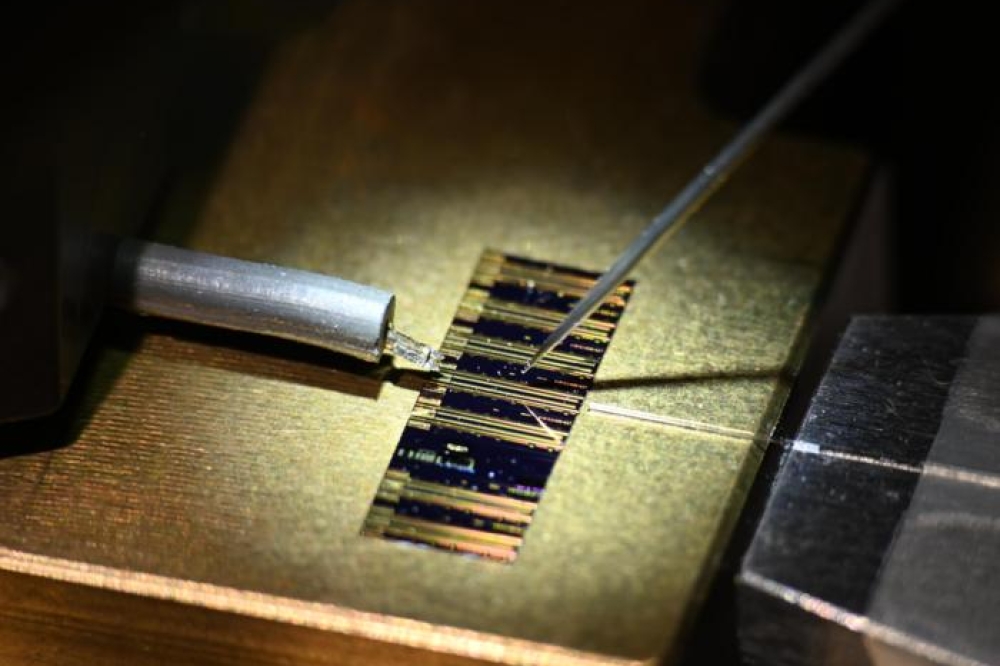
Typical bare epiwafer probing shows bright blue emission from a 200 mm diameter epiwafer prior to LED chip processing.

The EL spectra of 1 mm LED chips recorded under different injection currents showing peak emission at 455 nm. The multiple peaks are caused by Fabry-Perot cavity reflections under the EL micro-probe. The inset shows the typical emission from an LED driven at 20 mA.
The current-voltage plot of a thin film LED structure fabricated using GaN-on-silicon approach where the LED layers are cited on a thermal conductive copper host by a layer transfer process.
When we use AlGaN intermediate buffers, we have found that the concentration of the aluminium in these layers must be optimized to prevent post-process cracking of LED active layers, which can occur during substrate thinning and nitride buffer removal. Get this right, optimise the doping and incorporate surface roughening, and it is possible to realize a high radiant flux on a large silicon platform.
Our efforts showcase the potential of blue LEDs on 200 mm silicon, a format that can unlock the door to affordable solid-state lighting. Fulfilling this promise requires the development of a stable foundry process, which delivers yields that are ideally superior to those associated with 150 mm sapphire and silicon substrates. One way to get there is to embark on more joint programs that unite the expertise in academia with that found in industry. We will participate, and hope that many others do too.
The team at IMRE Singapore led by Sudhiranjan Tripathy involves members: M. Krishna Kumar, S. B. Dolmanan, Y. Dikme, Vivian K. X. Lin, H. R. Tan, R. S. Kajen, L. K. Bera and S. L. Teo. The research team acknowledges support from Exploit Technology Pte Ltd and the TSRP GaN-on-Si Program of Science and the Engineering Research Council of A*STAR. Technical discussion with Armin Dadgar from the OVG-University-Magdeburg is also gratefully acknowledged.
Further reading
III–V Compound Semiconductors: Integration with Silicon-Based Microelectronics, CRC Press, T. K. Li, M. Mastro, and A. Dadgar, Parkway NW (2010).
T. Egawa et. al., J. Phys. D: Appl. Phys. 43 354008 (2010).
D. Zhu et al., J. Appl. Phys. 109 014502 (2011).
E. Llado et al., J. Appl. Phys. 108 114501 (2010).
S. B. Dolmanan et. al., Electrochem. Solid State Lett. 14 H460 (201