News Article
Composite oxide promises to aid III-V MOSFETs
A high-performance gate dielectric can be formed with a stack of interleaving La2O3 and HfO2 layers that are subsequently annealed at 500 °C.

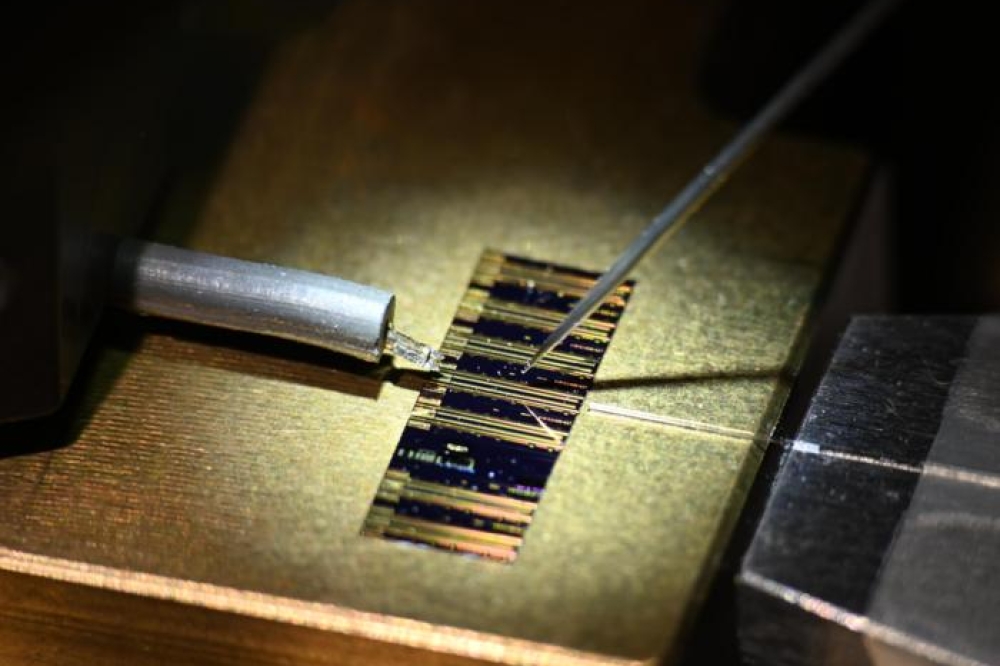
Capacitance-voltage plots for the InGaAs MOS-capacitor with a composite oxide built from five interleaved layers of 0.8 nm-thick La2O3 and 0.8 nm-thick HfO2. Annealing temperatures varied from 400 oC (a) to 500 oC (b) and 550 oC (c)
Progressof III-V MOSFETs, which are tipped to play a major role in extending Moore’s Law well beyond the 10 nm node, is held back by the lack of a high-quality gate dielectric. But recent work by a partnership between engineers at National Chiao Tung University in Taiwan, Tokyo University, and TMSC, shows that a composite oxide made from the pairing of La2O3 and HfO2 could address this weakness.
Interleaving 0.8 nm-thick films of both these oxides to form a stack on InGaAs has created a metal-oxide-semiconductor (MOS) capacitor with a high capacitance, low leakage current and relatively few interface traps.
The attractive attributes of La2O3 have been known for some time. It has a comparable dielectric constant to HfO2, the oxide that the silicon industry uses today for making its leading chips, but has a higher temperature for recrystallization. Films that are amorphous, rather than crystalline, are preferable for dielectrics, because they have a higher dielectric constant and thus enable a lower leakage current.
However, growth of La2O3 on InGaAs does have a downside: It leads to strong inter-diffusion between these two materials after post-deposition annealing. So a diffusion barrier needs to be inserted. And according to the Taiwan-Japan team, HfO2 is a very good candidate, because it has a high-energy bandgap and can demonstrate inversion behaviour with InGaAs.
To test the capability of the pairing of La2O3 and HfO2 on InGaAs, the team used molecular beam deposition to form a series of MOS capacitors, which were subjected to different annealing temperatures.
“Molecular beam deposition is an ultra-high vacuum system,” says Edward Chang from National Chiao Tung University, Taiwan, who explains that the oxides were deposited by electron-beam evaporation.
Surface cleaning occurred prior to oxide deposition on the 100 nm-thick film of n-type In0.53Ga0.47As. Wafers were cleaned in 4 percent HCl for 3 minutes, before they were dipped in (NH4)2S for 30 minutes.
Wafers were then transferred to the molecular beam deposition tool, and five layers of 0.8 nm-thick HfO2, interlaced with 0.8 nm-thick La2O3, were grown at 300 °C. Epiwafers were subsequently annealed in nitrogen gas for 5 minutes at either 400 °C, 500 °C or 550 °C, before a Ni/Au gate contact and a Au/Ge/Ni/Au back contact were added.
Photoelectron spectroscopy revealed compositional and interfacial properties of the epitaxial stacks. Increasing the annealing temperature was found to: reduced the number of As-As bonds; decrease the number of oxides associated with arsenic, gallium and indium; and increase the amount of La2O3 at an annealing temperature of 500 °C.
Oxide levels are thought to decrease at higher temperatures, due to the conversion of As-O, Ga-O and In-O bonds to InAs, GaAs and La2O3. However, cranking up the annealing temperature from 500 °C to 550 °C has a downside, leading to an increase in oxides associated with arsenic, gallium and indium, which occur due to diffusion of these atoms into the oxide layers.
Plots of capacitance as a function of voltage were obtained for devices formed at all three annealing temperatures (see Figure). The device formed by annealing at 400 °C shows abnormal accumulation capacitance at lower frequencies, which is thought to result from a higher leakage current and a higher density of traps at the interface. These are not issues for the device formed by annealing at 500 °C, which has superior electrical characteristics compared to the control – an 8 nm film of HfO2 on In0.53Ga0.47As.
The capacitance equivalent thickness – the thickness to produce the same capacitance as 1 nm of SiO2 – is 2.2 nm for the device with the composite oxide, compared to 2.7 nm for HfO2. What’s more, compared to this control, frequency dispersion is lower, falling from 5.1 percent to 3.5 percent.
Annealing temperature impacts the density of interface traps, which fell with increasing temperature, plummeting from more than 1013 cm-2 eV-1 at 400 °C to 7 x 1011 cm-2 eV-1 at 500 °C. A higher annealing temperature of 550 °C did not lead to a further cut in the density of interface traps – instead this figure increased to 9 x 1011 cm-2 eV-1. In comparison, the control sample had a interface trap density of 2.4 x 1012 cm-2 eV-1.
The next goal for the team is to use this composite oxide to fabricate a MOSFET and a MOSHEMT.
Y. C. Lin et. al.
IEEE Electron. Dev. Lett. 34 1229 (2013)