Technical Insight
Scrutinising VCSELs by SIMS
An advanced form of SIMS identifies dopants, impurities, compositions and thicknesses in various layers of VCSEL structures
BY TEMEL BÜYÜKLIMANLI, CHARLES MAGEE, JEFFREY SERFASS AND JEFFREY KIPNIS FROM EVANS ANALYTICAL GROUP

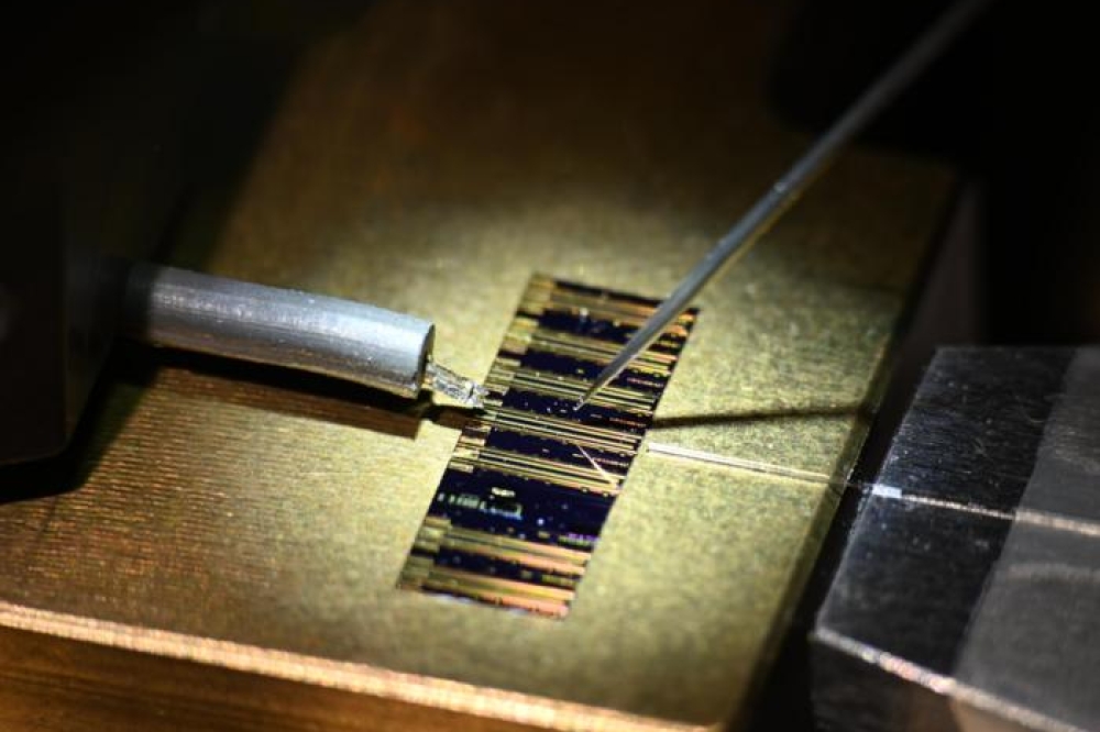
A SIMS scientist places a sample into the SIMS tool.
The VCSEL has several advantages over its edge-emitting cousin. Its strengths include a higher modulation speed, on-wafer testing and the emission of a symmetrical emission pattern that is oriented perpendicular to the surface. This form of emission, which is also produced when devices are configured in a two-dimensional array, is ideal for coupling into other optical components.
However, all these merits over the edge-emitting laser come at the expense of a more complex device architecture. With a VCSEL, resonator mirrors have to fulfil two roles: like an edge-emitter, they have to control the extent of optical feedback and light output; but in addition, they also have to be electrically conducting, so that they can aid the injection of carriers from the contacts into the active region.
This set of requirements is often met by forming a stack of semiconductor layers, which have thicknesses that are carefully chosen to create a distributed Bragg reflector (DBR). To produce a high performance VCSEL, the DBR is formed from alternating layers with a sufficiently high refractive index contrast to realise high levels of reflection. Engineers must also ensure that the conductivity of the mirrors is sufficiently high to prevent current injection into the active region from causing excessive ohmic heating.
High-efficiency VCSELs are possible when these mirrors form part of a structure with a high degree of optical and electrical confinement. Such a device may be built from more than 200 layers, some of which can contain grading of both the doping level and the alloy composition. Growth of such a structure is very challenging, so process engineers support their efforts by using a variety of characterisation techniques to uncover details associated with the epilayers, such as their thickness, doping and composition. While some approaches can only offer insights into a few of these characteristics, one is capable of delivering a great deal of detail about these structure – it is a variant of secondary ion mass spectrometry, known as Point-by-point CORrected SIMS, or PCOR-SIMS. Pioneered by our team at Evans Analytical Group, this technique can measure layer thickness, composition and doping profile more accurately than regular SIMS, where calibration with respect to alloy composition is not made at every data point (see Figure 1).

Figure 1. PCOR-SIMS pioneered by Evans Analytical Group can provide a depth profile of a full VCSEL structure. All of the profiles were acquired in a single analysis. Boron profile marks the beginning of the substrate.
Our development of PCOR-SIMS can be traced back to the late 1990s when we were faced with acquiring accurate profiles for both dopants and matrix elements in SiGe materials. Previous to this time, it was commonly assumed that SIMS could not quantify matrix-level concentrations, and there was no way to change dopant sensitivities continuously based on matrix composition (because it was thought that SIMS could not measure matrix composition). While PCOR-SIMS did not require any instrument modifications, many test samples had to be fabricated and analysed by other techniques. These samples formed the basis for the empirical relationships between sensitivity and concentration that are the underpinnings of the PCOR-SIMS methodology. In addition, other techniques, both nuclear and TEM-based, were used to verify the accuracy of the final PCOR-SIMS results.
One of the biggest challenges associated with the application of SIMS to the analysis of AlGaAs/GaAs VCSELs is that variations in aluminium content impact the sensitivity of aluminium. This means that the quantitative analysis of aluminium content is not straightforward. Complicating matters further, changes in alloy composition affect the sensitivity of the dopant species measured in the depth profile.
PCOR-SIMS addresses these issues by employing empirically derived analytical functions to correct for the well-known ‘SIMS matrix effect’, which comes into play when one deals with materials that are dissimilar in nature. In addition, this advanced variant of SIMS can account for changes in dopant sensitivity – these can be as much as a factor of two. The difference between traditional SIMS – where a single sensitivity is used in all layers – and PCOR-SIMS is illustrated in Figure 2. This shows the results of attempts to measure the silicon doping profile in an n-type DBR.

Figure 2. The PCOR-SIMS technique pioneered by Evans Analytical Group is capable of accurate measurements of the silicon concentration, independent of the proportion of aluminium in an n-DBR layer.
Perfecting the VCSEL
Producing a very high performance VCSEL requires optimisation of various aspects of the device, including: the aluminium composition and gradient between high and low refractive index mirror layers; the dopant profile between mirror layers; the composition of the aperture layer (assuming it is an oxide-confined VCSEL); the active layer impurity content; the aluminium grading on either side of the active layer; and, of course, the thicknesses of all of the layers within the structure.
An example of a PCOR-SIMS depth profile of a complete VCSEL structure is shown in Figure 1. This particular wafer uses a carbon-doped p-type AlGaAs DBR, a silicon-doped n-type AlGaAs DBR and an un-doped, low-aluminium AlGaAs active layer with multi-quantum well.
If the DBR is to provide good current injection, it must have a low electrical resistance. Realising this in a manner that produces a good device is not trivial. Large energy band offsets between the low and high index semiconductor layers of the DBR can inhibit current flow, particularly for p-type DBRs – and the obvious solution of increasing the doping to trim resistance is not an option because this increases optical absorption.
A far better approach is to grade the AlGaAs composition at the interfaces, while varying the doping profiles at these points. In due course we will show how PCOR-SIMS is uniquely capable of measuring subtle alloy grading and interface doping profiles.
To obtain a high efficiency and low threshold current, the VCSEL has to confine both the carriers and the transverse optical modes. Today, this is often realised in AlGaAs VCSELs through the selective oxidation of an AlGaAs layer, which is near the active layer (this creates so-called ‘oxide-confined’ VCSELs). One challenge with this design is to control the oxidation of these layers: to form the confining aperture correctly and reproducibly, the composition of the Al0.98Ga0.02As layer must be controlled to 1 percent. Later in this article, we will demonstrate how PCOR-SIMS can aid the wafer grower, by measuring the composition of the AlGaAs layer with sufficient precision and accuracy.
Obviously, another pre-requisite for the successful growth of a VCSEL epiwafer is to accurately control the thicknesses of the many layers that make up a working device. Nowhere is this more important than in the DBR, where the thicknesses must be correct to tailor the optical properties of the mirrors.
However, one must not neglect the importance of obtaining the correct thickness for the cladding and active layers, because this is needed to place the lasing mode optimally with respect to the boundaries of the 1-optical cavity. As we will soon see, if the growth engineer turns to PCOR-SIMS, they can correctly measure the composition of each layer, and use this to determine the correct layer thicknesses.
Scrutinising the structure
We have used our novel PCOR-SIMS technique to analyse a VCSEL structure with a carbon-doped p-type AlGaAs DBR, a silicon-doped n-type AlGaAs DBR and an un-doped, low-aluminium AlGaAs active layer containing a multi-quantum well. In the remainder of this article, we will show how our technique can offer insights into the alloy composition profile, the DBR dopant profiles, and various details associated with the active layer.
As previously mentioned, grading the alloy composition between the low and high index layers can trim the resistance of the DBR. With our PCOR-SIMS technique, it is possible to hone in on this part of the structure − see Figure 3 for a higher-depth-resolution profile of the top 200 nm of the sample – and reveal the compositional grading.
This occurs because the aluminium and gallium are not simply ‘switched on or off’, but varied in a precisely controlled manner to optimise the optical and electrical properties of the interfaces. Measurements with PCOR-SIMS have determined the aluminium content correctly over the entire range of composition, from 8 percent to 83 percent aluminium. The accuracy of these measurements has been verified against Standard Reference Material 2841 (Al0.1982±0.0014Ga0.8018As) from the National Institute of Standards and Technology and a Rutherford Backscattering Spectrometry calibrated, multi-composition AlGaAs reference material.
Further reductions in the resistance of the p-type DBR are possible by doping the mirrors with carbon, which has a sensitivity that is significantly affected by the alloy composition. However, with PCOR-SIMS we can correct for these effects at every data point, because the aluminium composition is measured for every carbon data point. Such an approach uncovers a high-concentration carbon-doping spike in some structures, which is near, but not exactly at, the interface between the low index layer with a higher aluminium content and the high index layer (see Figure 3).

Figure 3. Accurate carbon concentration and depth placement in AlGaAs layers with a graded composition.
We are confident that the placement of the carbon-doping spike is correct, because all of the profiles were acquired in the same analysis. Note that the low-level carbon dopant peaks may originate from a non-uniformity in doping, while the wafer was rotated during layer growth.
To provide current and optical confinement, producers of VCSELs tend to introduce a high-aluminium-content aperture, which is oxidised from the outside inwards. Halting the process at an appropriate point leaves an unoxidized ‘aperture’ through which current and light can pass. Obviously, to have a repeatable oxidation process, the rate of oxidation must not vary. This implies that there must be stringent compositional control and uniformity for the AlGaAs layer, because oxidation rates can vary by more than two orders of magnitude when aluminium content is increased from Al0.82Ga0.18As to Al1.0Ga0As.
With PCOR-SIMS, the aluminium composition in high-aluminium-content AlGaAs layers, such as those used in forming aperture layers, can be determined with a high level of precision (see Figure 4). In these samples, the difference in aluminium content is only 1.8 percent of the of the Group III composition – or 0.9 percent of total atoms −but the spread in the measurement values of either film is much less.
This degree of precision is crucial in perfecting these aperture layers.

Figure 4. PCOR-SIMS is capable of determining the composition of AlGaAs with high precision.
PCOR-SIMS can also offer insights into the structure of the active region (see Figure 5). It can reveal the aluminium profile, which varies on both sides of the active layer. There is grading from the p-type aperture layer, and also from then-type DBR to the cladding layers, where it is followed by a steep drop in aluminium content, which is lower in the barrier layers immediately surrounding the AlGaAs active layer. A detailed picture of the active region is also helpful for assessing whether the lasing mode in the optical cavity is in the optimal position.

Figure 5. Depth profile of the active region detail: (a) aperture layer composition; (b) gradient in cladding layer aluminium content; (c) cladding layer dopant concentration; (d) diffused doping in a multi-quantum well. Note, the carbon prfile is seen more clearly in Figure 2.
The pofile of the active region in Figure 5 also details the carbon doping for the active region and the mirror pairs nearby. By measuring carbon and silicon concentrations accurately in the n-type DBR with PCOR-SIMS, it is possible to determine the amount of p-type counter-doping that the inadvertent carbon contamination causes in the n-type layers.
Another strength of PCOR-SIMS is its ability to profile unwanted contamination species. The most ubiquitous of these is oxygen, which can produce contamination spikes at the growth transition between the low index and the higher index layers of a p-type DBR (see Figure 6). Knowing the exact location of the oxygen spike in the growth sequence is often helpful when trying to isolate and eliminate the source of contamination.

Figure 6. PCOS-SIMS can reveal oxygen contamination spike at DBR interfaces.
Occasionally, VCSELs contain sulphur impurities, which are believed to affect performance. The level of sulphur is higher in p-DBRs than n-DBRs, because it tracks the proportion of aluminium content (see Figure 7). The peak in the upper graded AlGaAs cladding layer is easier to spot in higher resolution reanalysis of the active region (Figure 8).

Figure 7. Sulphur impurities, which may degrade VCSEL performance, can be detected in many layers of this VCSEL structure.

Figure 8. A peaking sulphur impurity is detected in upper AlGaAs cladding layer.
Determining the correct layer thickness with conventional SIMS is not easy, because changes in alloy composition alter the sputtering rate at the surface. If no corrections are made, the plotted layer thickness can be in error by 20 percent for an AlGaAs VCSEL (see Figure 9).

Figure 9. A depth profile of an AlGaAs DBR layer, showing the PCOR-SIMS layer-thickness correction.
With PCOR-SIMS this weakness is addressed with an empirically derived sputtering-rate function. This determines the instantaneous sputtering rate for each data point based on the measured aluminium content − or indium content for InGaAs active layers − for that data point. Armed with this approach, compensation corrections are made for variations in sputtering rate throughout the VCSEL.
Our development of an advanced form of SIMS has opened up the capabilities of this technique so that it is no longer limited to impurity and dopant analyses of semiconductor materials. This effort has enabled PCOR-SIMS to be the most valuable tool for the growers of VCSELs: It can used for various important tasks, including uncovering doping levels in graded layers and delivering precise values for the aluminium composition in AlGaAs aperture layers.
Further reading
Reiner et al. IEEE Photon. Technol. Lett. 7 730 (1995)
https://www-s.nist.gov/srmors/view_detail.cfm?srm=2841
Sadao Adachi J. Appl. Phys. 58 R1 (1985)
K. D. Choquette et al., Electron. Lett. 30 2043 (1994))
http://www.eag.com/documents/BRO16.pdf