

Efficient enlargement of bulk AlN
Introducing expansion angles in excess of 45 degrees can slash the time it takes to realise bulk AlN grown by physical vapour transport with industrially relevant crystal diameters.
BY CARSTEN HARTMANN AND THOMAS STRAUBINGER FROM THE LEIBNIZ INSTITUTE FOR CRYSTAL GROWTH
The ultra wide band gap semiconductor AlN, as well as its ternary cousin AlGaN, has a number of attributes that make this material system a promising one for electronic and optoelectronic devices. This class of nitrides can withstand harsh conditions and high temperatures, and thanks to the very wide bandgap, can be used to make LEDs that emit in the deep and far UVC. The largest markets for such devices, which span 220 nm to 280 nm, are the disinfection of drinking water and waste water treatment. However, emission in this spectral range can also be deployed for surface sterilisation and bio-chemical sensing. As well as these opportunities in deep-UV photonics, AlN-based devices are compelling candidates for next-generation high-frequency power-conversion. Already, AlN-based high-power transistors are outperforming those made from the two most common wide bandgap semiconductors, SiC and GaN.
Due to a lack of native substrates, researchers exploring the capability of AlN and its alloys began by using sapphire substrates for the development of epitaxial layers. However, even when they turned to complex processing steps, the threading dislocation densities in the AlGaN layers remained high – typically in excess of 1 x 108 cm-2. The high density of these threading dislocations is one of the primary reasons why the potential of the AlN material system is yet to be fully exploited.
The power of PVT
Offering a promising way forward is the growth of AlN crystals by Physical Vapour Transport (PVT). In recent years, this approach to the growth of AlN with a high degree of crystallinity has advanced significantly, laying the foundation for substantial improvements in device performance. Successes include the fabrication of electrically injected deep-UV laser diodes and LEDs with high output power over long lifetimes.
Pioneers of AlN substrates produced by PVT include Hexatech Inc., which has introduced AlN substrates with diameters of up to 2 inches and threading dislocation densities below 1 x 104 cm-2. Hexatech is offering this material to selected scientific partners.
Another provider is Crystal IS, which demonstrated 4-inch AlN substrates with an 80 percent useable area earlier this year, and makes 3-inch AlN substrates for internal use.
For both these trailblazers, progress has been slow and hard won. To increase the diameter of the AlN crystals to the size they are today, engineers at these companies have devoted more than a decade to producing generation after generation of crystals, each with a larger diameter. Increases in size have come from dynamic growth of unfaceted regions. This enlargement, occurring at the beginning of crystal growth (cone-shaped), is restricted to small expansion angles.
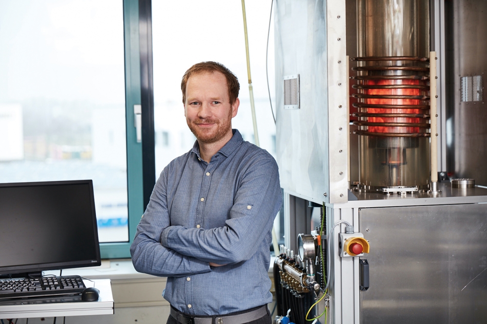
Our team at IKZ – that’s the common shorthand for the Leibniz Institute for Crystal Growth in Berlin, Germany – has developed an approach that overcomes this restriction. PVT is also used to grow our bulk AlN crystals, produced with an inductively heated graphite setup (see Figure 1).

Figure 1. (a) A sketch of the setup, with four identical PVT reactors
built at IKZ. (b) one shown here with opened housing for a better view
of the heated setup. For more details see C. Hartmann et al. Cryst. Eng.
Comm. 18 3488 (2016).
A foundation for our latest success is our expertise acquired through the growth of SiC boules by PVT. When moving from SiC to AlN growth we retained the reactor, the thermal insulation felt (carbon-bonded carbon fibre), and large parts of the graphite components. The growth temperature for both materials is around 2200 °C.
One key difference between the growth of AlN and SiC is the ambient atmosphere. For SiC, an argon atmosphere below 50 mbar is employed, while for AlN its N2 at a pressure of more than 400 mbar. Crucibles also differ, with graphite used for the growth of SiC, and tungsten or TaC used for AlN. Note that these two options are the only refractory materials capable of withstanding the reactive aluminium vapour under growth conditions.
To produce a high-purity AlN source – it contains less than 150 ppm wt oxygen – we start with a commercially available AlN powder and apply multiple sublimation–recrystallisation steps. During crystal growth, this source, located in the lower part of the crucible, decomposes gradually into aluminium and N2 vapor species. The aluminium vapour pressure in the crucible depends on the temperature, and typically ranges from 50 mbar to 150 mbar – one may imagine an aluminium ‘fog’ inside the N2 ambient. During growth, gaseous aluminium species diffuses along the concentration and temperature gradient through the nitrogen ambient in the growth space, before re-condensing on the AlN seed.
Seeding the growth
Recently, we have developed a seed holder design that positions the seed on a TaC pedestal. With this arrangement, crystals grow freely without contact to parasitic grains (see Figure 2). This design allows high radial thermal gradients – the driving force for diameter expansion.

Figure 2. Simplified sketch of the seed holder design: TaC pedestal and
fully faceted grown crystal with an expansion angle of 45°. For more
details see C. Hartmann et al. Appl. Phys. Express 16 075502 (2023).
With this new configuration we have realised far higher lateral growth rates. At a seed temperature of 2230 °C growth rates are as fast as around 200 µm/h in both the N-polar and the prismatic m directions, resulting in huge expansion angles of around 45° along the entire crystal length.
The crystal habit consists of the (000.1) N-polar top facet, the (10.10) prismatic m facets, and (101x) rhombohedral r facets. The full diameter spans the entire crystal length, ensuring that all cut c-plane wafers have the same (final crystal) diameter.
AlN seeds with a diameter of 8 mm and a threading dislocation density below 1 x 103 cm-2 provided the starting point for this work. These first-generation seeds were prepared from spontaneous nucleated AlN crystals. Using our seeded process, growth on them produced crystals with a length of 5-7 mm and a diameter between 18-24 mm. With just two to three steps, we magnified dimensions, producing AlN crystals with diameters of more than 30 mm, which are very suitable for preparing 1-inch substrates (see Figure 3). Based on our current findings, we can’t foresee any obstacles to a fast scale-up to industrially relevant diameters of up to 4 inches or more.

Figure 3. Three AlN crystals of subsequent crystal generations (17 mm, 27 mm, and 37 mm in diameter).
If AlN substrates are to make a significant impact, a substantial increase in production speed and availability must go hand-in-hand with maintaining high material quality – note that the latter is possible, according to our characterisation. Measurements of symmetric 0002 and asymmetric 10.13 rocking curves on the -c facet of the crystals with an open detector aperture reveal typically a single sharp peak with a full-width at half-maximum of 11 arcsec (see Figure 4). Such a sharp peak is indicative of a high structural quality, including a low dislocation density and an absence of small-angle grain boundaries.
Often rocking curves are used to determine the dislocation density in wide bandgap materials and epilayers. However, this approach only provides meaningful results for dislocation densities down to 5 x 104 cm-2, as at lower dislocation densities there is no peak broadening compared with perfect, dislocation-free AlN. Another issue is that bulk crystals often show inhomogeneously distributed dislocation densities, having wide areas with very few dislocations and local dislocation clusters. It’s not possible to uncover the details of these variations with rocking curves, which only offer an average over the recorded area. To identify the lateral dislocation distribution, one can turn to X-ray topography or defect-selective etching.
We have scrutinised an m-plane sample cut from a seeded crystal with a 20 mm diameter using white-beam X-ray topography. This involved the selection of the 11.22 reflection, which is sensitive to all possible types of dislocations (a, c, and a+c type).

Figure 4. Double crystal rocking curves (semi logarithmic scale) measured
with open detector aperture in the 0002 (a) and 1013 reflection (b).
From this form of X-ray topography, we have established that the entire -c grown domain of this sample is dislocation free. The only dislocations that exist are in the m domain near the -c/m boundary and in the r domain. We find that dislocations start at the seed rim and stay in the m area without crossing the -c/m domain boundary. So far, we are yet to determine the origin of these dislocations. Possible explanations include: insufficient polishing quality at the seed rim; unfavourable initial growth conditions, such as gradients that are too large, at the seed rim; and contact between the r domain and the seed holder. We have also observed additional contrast features at several domain boundaries and within the m domain, caused by strain that stems from different impurity concentrations.
To obtain defect information over the entire diameter, we prepared a wafer from a crystal 34 mm in diameter. We characterised the wafer with defect-selective etching (see Figure 6). With this technique we determined that the medium etch-pit density, using a standardised 21-point measurement, is 5 x 103 cm-2 inside the 25 mm target diameter. We also uncovered a linear arrangement of dislocations, occurring at the domain boundary between the -c and m grown domains. The origin of the associated etch pits can be traced back to dislocations formed at the seed rim, which continued along the -c/m boundary in the m domain (compare with Figure 5 (c)).
Recently, we have been pursuing further diameter enlargement of our AlN crystals. Our efforts have involved selecting the c-plane wafer close to the top of the crystal, where the -c/m boundary is close to the crystal edge, and using a seed diameter that gets as close as possible, but below, the -c/m boundary. This approach promises to provide a shortcut to the development of commercial substrates with a diameter of 100 mm or more.

Figure 5. (a) A sketch with a highlighted area of an m-plane sample
prepared from a seeded crystal with diameter of 20 mm; (b) Transmission
photograph of a 1 mm-thick cross-section m plane sample. The several
growth domains (-c, m, and r) are distinguishable by the different
colours. (c) White-Beam X-Ray Topography (WB-XRT) stitched images (11.22
reflection) of the cross-section sample. No dislocations are visible in
the -c grown domain (1). Dislocations exist only in the m domain near
the -c/m boundary (2). Further dislocations exist in the upper part of
the m domain (3) and in the r domain (4). The lower half of the sample
is dislocation free. Strain contrasts are visible at the domain
boundaries (5,6,7) and within the m-domain (8). For more details see C.
Hartmann et al. Appl. Phys. Express 16 075502 (2023). The WB-XRT image
was recorded by Merve Pinar Kabukcuoglu, Elias Hamann, and Daniel
Hänschke from the Institute for Photon Science and Synchrotron
Radiation, Karlsruhe Institute of Technology. We thank the Institute for
Beam Physics and Technology for the operation of the storage ring, the
Karlsruhe Research Accelerator.
One of the highlights of our work on AlN is the fabrication of an epi-ready 25 mm substrate with an m flat (see Figure 7 (a)). The entire substrate area is grown on the -c facet, clearly identified by homogeneous yellowish colouring. To produce this substrate, our team in our preparation lab developed a complete AlN preparation line, beginning with the sawing of c-plane wafers and including lapping, mechanical polishing and chemo-mechanical polishing. The latter form of polishing using silica under basic conditions ensures a root-mean-square surface roughness below 0.3 nm (see Figure 7 (b)). Encouragingly, when MOCVD is used to grow pseudomorphically homoepitaxial layers on this substrate, the epilayer matches the quality of its foundation (see Figure 7 (c)). We can adjust the substrate off-cut – this mainly determines the step widths/macro step formation – precisely between 0.05 and 0.5 degrees.

Figure 6. Defect selective etched AlN wafer with a diameter of 34 mm an
average etch pitch density of 5 x 103 cm-2 inside the 25 mm target
diameter. The -c/m domain boundary with an increased etch-pit density is
outside of the 25 mm target diameter (green square). For more details
see C. Hartmann et al. Appl. Phys. Express 16 075502 (2023).
Our institution is now selling epi-ready single crystalline wafers with a diameter of 10 mm. These substrates are divided into a range of grades, with some better suited to research purposes and others more aligned to technology development.
By the end of next year, we hope to offer 1-inch prototype substrates and 2-inch demonstrators. We are also keen to investigate the performance of devices that are built on our substrates, and are open to project ideas for AlN-based opto-electronic or high-power devices. In such a collaboration we will be able to provide AlN substrates with diameters presently up to 1-inch that feature tailored optical, electrical and structural properties.
Figure 7. (a) 25 mm epi ready Al-polar AlN substrate; (b) atomic force microscopy (AFM) image of Al-polar epi-ready surface after chemo-mechanical polishing (off-cut of 0.4°); (c) AFM image of a 5 µm-thick Al-polar AlN epi layer (off-cut of 0.4°) grown by MOCVD. We thank Marcel Schilling, Tim Wernicke, and Michael Kneissl from the TU Berlin (section ‘Experimental Nanophysics and Photonics’) for the homoepitaxial growth of the AlN epi layers and the recording of the
AFM images.
Further reading
C. Hartmann et al. “Efficient diameter enlargement of bulk AlN single crystals with high structural quality” Appl. Phys. Express 16 075502 (2023)
C. Hartmann et al. “Favourable growth conditions for the preparation of bulk AlN single crystals by PVT” Cryst. Eng. Comm. 22 1762 (2020)
R. Dalmau et al. X-Ray “Topography Characterization of Large Diameter AlN Single Crystal Substrates” Mater. Sci. Forum 1004 63 (2020)
R. T. Bondokov et al. (Invited) “Development of 3-inch AlN Single Crystal Substrates” ECS Trans. 109 13 (2022)
H. Amano et al. “The 2020 UV emitter roadmap” J. Phys. D: Appl. Phys. 53 503001 (2020)
J. Kotani et al. “24.4 W/mm X-Band GaN HEMTs on AlN Substrates With the LPCVD-Grown High-Breakdown-Field SiNx Layer” IEEE J. Electron Devices Soc. 11 101 (2023)


