GaN reaches new power levels
2DEG formation In GaAs- or InP-based HEMTs, a doped donor layer is required to form the two dimensional electron gas (2DEG) at the heterojunction. No doped donor layer is required in GaN HEMTs in order to supply charge. When grown on the Ga-face, along the C axis of the wurtzite crystal, a positive polarization charge is generated. This is approximately equal to 5.5 x 1013 cm-2 times the electronic charge multiplied by the Al fractional content in the AlxGa1-xN top barrier layer. With a surface conduction band potential of about (1.0 + 1.9x) volts, which puts it 1.6 eV above the Fermi energy for the 30% Al concentration typically used in these devices, a 2DEG of about 1 x 1013 cm-2 is induced in the GaN near the heterojunction. This charge is lower by 20-30% than that predicted by theory, and this is due to surface depletion effects and the charge effects created by the high level of dislocations present in GaN. HEMT devices fabricated with undoped AlGaN barriers typically exhibit electron mobility values in the 1200-1700 cm2/Vs range, and average electron transit velocities of 1.2-1.3 x 107 cm/s. GaN epitaxy While GaAs and InP substrates can be used to grow lattice-matched alloys, there is no suitable lattice-matched substrate for GaN growth. SiC is generally used for HEMT applications, particularly for high-power devices where its heat conductivity of 3.3 Wcm-1 K-1 (10 times higher than sapphire, another possible substrate) means heat is readily removed. However, the lattice mismatch between GaN and SiC typically results in the GaN HEMT exhibiting 2-5 x 108 cm-2 threading dislocations. These generate 4 x 107 cm-1 charged states that act to decrease the polarization-induced charge. Other than a slight decrease in channel charge, these dislocations do not negatively impact HEMT performance. MOVPE or MBE can be used to grow AlGaN/GaN HEMTs, though most reported results are on MOVPE-grown material. To obtain device-quality material, it is critical that growth be done on a Ga-face surface. MOVPE growth exhibits a Ga-face surface during typical growth conditions. For MBE growth, a N- or Ga-face may occur when growth is initiated on sapphire substrates. A combination of a thin (7 nm) AlN nucleation layer and an Al-rich sapphire surface is required for Ga-polarity surfaces in MBE. N is supplied during MBE growth by an RF plasma source producing atomic nitrogen. Sapphire substrates are heated using a coating of tungsten to act as a radiation absorber. GaN growth by MBE is typically done at 800 °C and at a rate of 0.5 µm/h. Under these conditions, significant Ga desorption takes place. The Ga/N ratio is carefully optimized so that within the substrate temperature non-uniformity, the cooler edge of the wafer is Ga-rich and the hotter center of the wafer is N-rich.
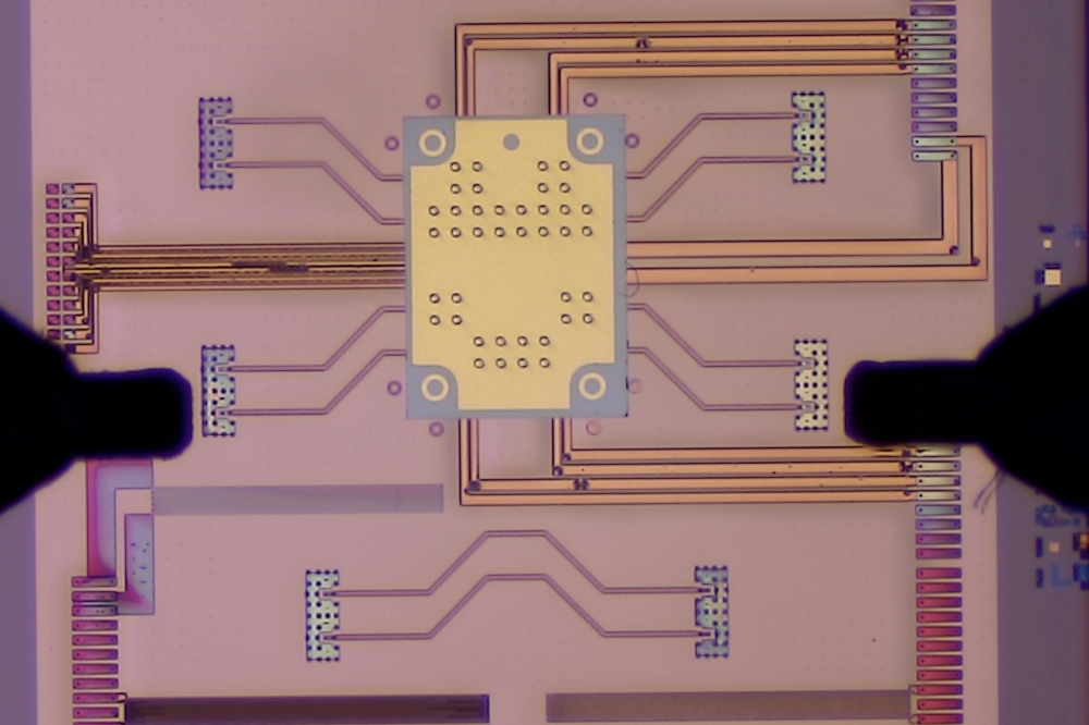
MOVPE growth performed at Cornell is done using flow-modulation techniques in a custom-built, cold-wall, multi-wafer quartz reactor, at a pressure of 76 torr and a substrate temperature of 1040 °C. The precursors used are triethylgallium, trimethylaluminum and ammonia with V/III ratios set at 1800 for GaN and 900-1800 for AlGaN. A single-step, high-temperature nucleation process is utilized that produces atomically smooth, planar films within the first several hundred Angstroms of growth on both sapphire and SiC substrates. It has been found that establishing a 2-D growth front as early as possible is crucial in achieving the insulating GaN films critical for HEMT device operation. HEMT fabrication A typical layer structure used for the fabrication of AlGaN/GaN HEMTs has a 5-20 nm AlN or AlGaN nucleation layer, a 2-3 µm unintentionally doped (UID) GaN buffer and a 25 nm UID Al0.3Ga0.7N barrier. A GaN cap of 2-3 nm can also be grown to increase the effective Schottky barrier, which improves breakdown characteristics and decreases the gate leakage. A Cl2-based electron cyclotron resonance process is used to define isolated mesas, which typically have a final height of 200 nm. E-beam lithography is used to define the ohmic contacts. This avoids the loss of 2DEG charge during optical lithography, which can occur when using hydroxyl-based optical developers. These chemicals attack the GaN surface and dislocations, reducing charge. A two-layer resist lift-off process and E-beam evaporation is used for ohmic metalization that consists of a Ti/Al/Ti/Au (20 nm/100 nm/45 nm/55 nm) composite, followed by a 30-60 s anneal at 800 °C. Typical contact resistances for this process range from 0.3 to 0.5 Ωmm. Ni/Au (20 nm/360 nm) E-beam defined mushroom gates with gate lengths ranging from 0.15 to 0.6 µm are used, followed by Ti/Au (20 nm/360 nm) contact pads. Finally, a 100 nm Si3N4 surface passivation layer is deposited by PECVD, a critical step that can double or even triple the output power of the device. The finished structure is shown in figure 1. For a 0.35 µm gate length, the HEMT exhibits a breakdown voltage of 70 V, an ft of 35 GHz and an Ids of 1 A/mm.
In structures with such large 2DEG concentrations (1-2 x 1013 cm-2) it is critical that attention is paid to the gate s ability to pinch-off this charge. For GaAs and InP, the ability to pinch-off the 2DEG can be enhanced by increasing the height of the barrier layer. However, for GaN-based HEMTs, an increase in the barrier height (by increasing Al content in the AlGaN barrier material) also increases the piezoelectric-induced charge, thereby making pinch-off harder to achieve. Because thermally assisted tunneling is a predomin-ant component of the leakage current at high temperatures, and for power applications the gate region will typically operate at about 300 °C, leakage needs to be determined at this temperature. Leakage current increases as Al content increases, with a typical value of 10-7 A/mm, a figure sufficiently low for power applications. However, this value can be significantly larger if the material and surface properties of the GaN are not optimized. Device performance Improvements in material and device fabrication have led to new performance limits for GaN HEMTs. For 0.15 µm gate-length devices using 25 nm barrier layers, the ft values of HEMTs fabricated on sapphire and SiC substrates are 74 and 106 GHz, respectively. Optimizing for power added efficiency results in a value of 78% for a 1.5 mm periphery device on sapphire operating at 1.8 W/mm. The gate-drain breakdown voltage depends almost linearly on the gate length, with gate-drain separation as another parameter. A breakdown voltage of 72 V was obtained for a HEMT with a gate length of 0.3 µm and a gate-to-drain spacing of 2.0 µm. The present normalized CW power density at 10 GHz is 11.2 W/mm for a 100 µm periphery device on SiC. In terms of noise performance, for a 0.3 µm device on SiC with a Vds of 8.1 V and a Vgs of -3.22 V, 1.4 dB was obtained at 10 GHz operation. In general, these limits have been obtained by trading off against another performance metric.
When these operating limits are combined with thermal conductivity simulations the operating limits of power HEMTs can be compared for several different material systems. This is shown in figure 2, where it can be seen that a GaN HEMT has the potential to deliver 56 times more power than a GaAs MESFET and 1.8 times more power than a SiC HEMT. Circuits Material growth, device processing and discrete HEMT performance are all necessary steps in the development of a technology that can be applied to high-power RF applications. However, it is still necessary to transfer this experience into the fabrication of circuits required for power generation - GaN-based circuitry is now entering into that phase, with power cells and amplifiers being demonstrated. Figure 3 shows the performance of a high gain cascode power cell using two 0.3 µm gate length HEMTs, each with gate widths of 1 mm. Operating in the cascode configuration provides approximately 7 dB of additional gain, enhanced small signal gain, and around 10 V of additional drain voltage swing. Using the cascode power cell as a building block, two such cells are used in the fabrication of the broadband amplifier in figure 4. With a die size of only 5 mm2, the amplifier exhibits a bandwidth of 9.5 GHz, and greater than 14 dB small signal gain. With these results it is clear that the potential offered by the GaN material system for power applications is becoming a reality.