Technical Insight
Slashing the cost of GaN HEMTs
Although silicon power transistors are inferior to their GaN rivals in many regards, they win hands-down in the metric that matters most: Cost. However, affordable GaN HEMTs are within reach, when production moves to 200 mm GaN-on-silicon epiwafers processed on standard CMOS lines, argues imec’s Brice De Jaeger, Marleen Van Hove and Stefaan Decoutere.

Wide bandgap power devices can be manufactured far more cheaply when processing is performed on 200 mm GaN-on-silicon with a CMOS-compatible process flow
GaN HEMTs are very promising devices for power electronics. Their combination of a high breakdown voltage, an ability to withstand high temperatures and a higher switching speed than comparable technologies gives them the potential to deliver cost reductions at the system level. For example, switching power electronics from silicon to GaN can trim the size and cost of a solar inverter by cutting the size and cost of passives – resistors, inductors and capacitors.
However, the benefit of trimming the bill for passives has to be weighed against the higher prices that GaN HEMTs sell for compared to silicon, the incumbent material for making power electronics. Today’s fabrication costs for manufacturing GaN HEMTs are much higher than those for silicon transistors, due to production on dedicated processing lines using small diameter substrates, often made from sapphire or SiC.
One obvious way to slash the manufacturing costs of GaN HEMTs is to move production to a high-productivity 200 mm CMOS fab, a step that must include the transfer of the epitaxial process to a silicon platform. To reap this reward, engineers must overcome three tough technical challenges: The deposition of defect-free, crack-free GaN epilayer stacks on 200 mm silicon; the processing of AlGaN/GaN HEMTs on 200 mm silicon wafers with a standard CMOS toolset, a requirement that prohibits the use of some materials that are often used in GaN transistor fabrication; and the development of a process flow that produces good-quality, high-performance, high-yielding devices.
At imec, an internationally renowned research centre based in Leuven, Belgium, we have been working with leading device manufacturers to solve all these challenges. This three-year effort has been hugely successful, and it has led to the demonstration of GaN-on-silicon power devices operating at high currents.
Scaling to 200 mm silicon
Fortunately, we did not have to develop our growth technology for depositing GaN layers on 200 mm silicon from scratch. Instead, we could build on the success of our processes for forming GaN-based epitaxial stacks on 4-inch and 6-inch silicon wafers. Thanks to this in-house expertise, we were able to make good progress during our development of MOCVD process for the growth of crack-free AlGaN/GaN/AlGaN double heterostructures on 200 mm silicon (111) substrates.
The double heterostructure that we form consists of a 200 nm AlN nucleation layer; a buffer stack comprising 400 nm Al0.75Ga0.25N, 400 nm Al0.50Ga0.50N and 1800 nm Al0.25Ga0.75N; a 150 nm GaN channel and a 10 nm Al0.25Ga0.75N barrier layer. A 2 nm-thick GaN capping layer is deposited on top of the Al0.25Ga0.75N barrier to prevent it from cracking during post-growth cool down. On that cap, we deposit a 120 nm Si3N4passivation layer by low-pressure CVD (LPCVD) at 750 °C.
This structure yields reproducible, uniform two-dimensional electron gas (2DEG) characteristics across the wafer. According to measurements on Van-der-Pauw structures, the average 2DEG sheet resistance on 18 wafers with an identical epilayer stack is 360 Ω /□, and the standard deviation is 5 percent (see Figure 1). Hall measurements reveal that the 2DEG carrier density is 8.9 x 1012cm-2and carrier mobility is 1950 cm2V-1s-1.

Figure 1. imec’s engineers can produce structures with a reproducible, uniform AlGaN/GaN 2DEG sheet resistance. Data is for 18 epilayers grown on 200 mm silicon substrates
The AlGaN/GaN/AlGaN epilayer stacks that we deposit are about 3 µm thick, and they are formed on 1.15 mm-thick silicon substrates. These are thicker than standard substrates (which are 0.725 mm thick), because a greater rigidity is needed to obtain acceptable wafer bow and wafer brittleness. Processing at imec’s 200 mm CMOS silicon line demands a wafer bow of 50 µm or less.
Our epiwafers that are formed on 1.15 mm-thick silicon wafers are, in general, suitable for processing on production tools that have not been subjected to significant hardware or process modifications. Occasionally, however, we had to make adjustments to the tools, such as slowing down the robot speed of the wafer transport systems so that they can accommodate the larger inertia of thicker silicon substrates. We also avoided direct loading of the wafers on the electrostatic chuck of our implantation system – instead, we mounted them on carrier wafers to prevent them from breaking.
Variations in wafer bow were tracked during device processing. Scrutinizing the data failed to uncover any significant addition to wafer bow during gate, ohmic, and aluminium interconnect processing. Adding thick copper interconnects introduces a tensile wafer bow, but this was limited to 40 µm or less. When modifications to the tools and bow monitoring were put in place, we experienced zero wafer loss during processing, according to standard fab operation procedures.
Preventing gallium contamination
Processing wafers with compound semiconductor stacks on 200 mm silicon lines requires careful planning. Owners of these foundries may have concerns, such as the fear that gallium can contaminate the processing tools – it is a p-type dopant in silicon.
To determine whether there is genuine cause for concern, we adopted existing procedures for contamination control, while monitoring and controlling the spread of gallium from the GaN wafers to the tools. On most tools, gallium levels on the front and backside of silicon wafers are always below 1 x 10¹¹atoms/cm2. One notable exception is the tools that etch the GaN layers, which are used for processes such as the AlGaN barrier recess etch. In this case, gallium levels can exceed 10 x 1011atoms/cm2. However, contamination can be held below 1 x 10¹¹atoms/cm2with an optimized chlorine-based cleaning procedure at 200 °C that involves the formation of volatile GaCl3.
In the labs and fabs used to make GaN devices today, processing tends to involve lift-off metallization schemes for defining ohmic and gate contacts. These contacts are built from either the pairing of nickel then gold or the combination of molybdenum then gold. In stark contrast, standard high-productivity CMOS fabs use gold-free metallization schemes, and dry etch patterning instead of lift-off.
It is a challenge to fabricate gold-free ohmic contacts with a contact resistance below 1.0 Ω mm. However, it is possible to get closer to this target with an AlGaN barrier recess in the ohmic areas, which is formed with a BCl3/SF6plasma at low bias power. This yields a contact resistance of 1.25 ± 0.15 Ω mm when a 5 nm-thick AlGaN barrier remains. In comparison, contact resistances exceed 4 Ω mm when a barrier recess is not employed. Our gold-free Ohmic contact stack consists of 20 nm of titanium, followed by 100 nm of aluminium, another 20 nm of titanium and 60 nm of TiN. This is alloyed at 550 °C for 90 s in a nitrogen gas atmosphere.

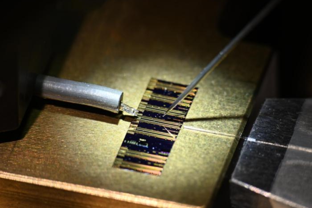
A fully processed 200 mm GaN-on silicon MISHEMT device wafer
Device demonstrations
To showcase the feasibility of processing AlGaN/GaN HEMTs on 200 mm GaN-on-silicon wafers, we have fabricated fully functional power devices with a 60 mm total gate width.
There are a wide variety of device architectures available to us, which could realise either depletion-mode (d-mode) or enhancement-mode (e-mode) power devices. We decided to focus on the latter class of device because this is a promising candidate for making reliable, high-performance, high-breakdown GaN power devices with normally off characteristics. Specifically, we fabricated an e-mode AlGaN/GaN metal-insulator-semiconductor HEMT (MISHEMT) with barrier recess and gate dielectric.
E-mode operation results from sufficiently recessing the AlGaN barrier in the gate areas, a step that reduces local polarization charge. To recess the Al0.25Ga0.75N barrier, we used a BCl3plasma at low bias power. Etching for 0 s, 30 s, and 60 s led to barrier recess depths of approximately 0 nm, 5 nm and 0 nm respectively. A barrier recess etch time of 60 s produced positive threshold voltages of 1.0 V ± 0.2 V over the full 200 mm wafer (see Figure 2).

Figure 2. The threshold voltage of the MISHEMT is influenced by the barrier recess etch time. Enhancement mode devices are obtained for 60 s barrier recess. The inset figure shows the corresponding ID-VGS characteristics
The gate leakage current of power devices can be suppressed by creating a MISHEMT structure in which a gate dielectric is inserted between the metal gate electrode and the AlGaN barrier to avoid the creation of a Schottky gate contact. However, we want to obtain devices with both a low gate leakage current and a high breakdown voltage, so the gate dielectric has to be carefully chosen.
Starting with a single layer of 15 nm atomic layer deposition (ALD) Al2O3, we measured breakdown values below the 600 V target. But with a bilayer of 5 nm 650 °C LPCVD Si3N4and 10 nm ALD Al2O3, we measured breakdown values above 600 V, close to the buffer breakdown values. This improved breakdown is most probably related to the higher-quality of the semiconductor/dielectric interface obtained with the Si3N4/Al2O3bilayer (see Figure 3).

Figure 3. Cross-section scanning electron microscopy images of the power device. The top figure shows the source-gate-drain finger configuration, which has 8 μm-thick source and drain copper interconnect layer encapsulated by Si3N4. The bottom picture details the source-gate area: The T-shaped metal gate electrode with the field plate, the gate dielectric, and the metallization stack in the ohmic source area
Power devices that we have produced as described above have a total gate width of 60 mm and consist of 60 gate fingers of 1 mm each. Gate length is 1.5 µm, gate-source distance is 0.75 µm and gate-drain distance is 10 µm. By extending the gate metallization by 1 µm to the drain side, we formed a gate-connected field plate. The devices delivered a maximum output current of 6 A at VGS= 8 V and VDS= 10 V. These results demonstrate the feasibility of AlGaN/GaN HEMT processing on 200 mm silicon substrates.
Our next step is to improve the characteristics of these transistors. At present, their performance lags that of our HEMTs made on 150 mm silicon wafers, which have a maximum output current of 8 A, a breakdown voltage of 750 V, a specific on-resistance of 2.9 mΩ cm2and an off-state drain leakage at 600 V of 7 µA.
There are no obvious barriers to replicating these results on 200 mm silicon wafers, and when we do that it will strengthen our claim that GaN-on-silicon wafers can combine affordability with a great set of characteristics. Silicon may be in the ascendancy in the market today, but it is going to face an ever increasing threat to its supremacy place from
GaN-on-silicon power electronics.
Further reading
K. Cheng et al.Appl. Phys. Express 5 011002 (2012) M. Van Hove et al. IEEE Electron Device Lett. 33 667 (2012) B. De Jaeger et al. Proceedings of 24th International Symposium on Power Semiconductor Devices and ICs, Bruges, Belgium, 3-7 June 2012, p. 49.