Advancing AlN and aluminium-rich AlGaN
High-quality epilayers with exceptional electrical quality are realised in Agnitron’s systems, including its new horizontal MOCVD reactor, the AgniGaN 400.
BY FIKADU ALEMA, WILLIAM BRAND, AARON FINE, VITALI SOUKHOVEEV AND ANDREI OSINSKY FROM AGNITRON
With a bandgap of just over 6 eV, AlN promises to provide ground-breaking power-electronic devices. But its success is stymied by difficulties in realising sufficiently high and stable free-carrier concentrations and mobilities in the device layers of diodes and transistors.
The most common dopant for realising n-type doping in AlN is silicon. Incorporating this element into AlN is relatively straightforward, but it does not behave as it does in GaN, where it forms a shallow donor. Instead, adding silicon to AlN creates deep defects, called DX centres. These defects are a menace, trapping electrons near the conduction-band edge, with activation energies ranging from 78 meV to 345 meV [1]. Due to this issue, only a small fraction of silicon dopants release free electrons at room temperature, hampering efforts to realise the carrier concentrations required for device operation.

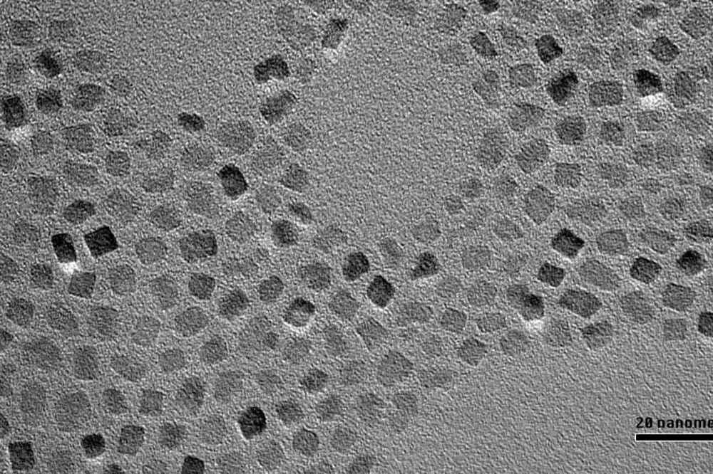
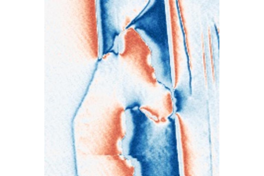
Figure 1. X-ray diffraction rocking curve (left) and a 2 µm × 2 µm atomic force microscopy image (right) of a 12 µm thick AlN film grown on a Crystal IS substrate using the RIS Agilis 100 reactor at Agnitron Technology.
To increase the n-type carrier concentration, engineers add more silicon to the AlN crystal. Initially this pays dividends, boosting the number of free electrons. However, there’s a limit to what’s possible, and beyond a certain level the free-carrier concentration falls. This occurs because higher doping levels introduce additional defects – such as vacancies and defect complexes – that trap or compensate for free electrons. Due to these deleterious effects, there’s a limit to how effectively AlN can be doped. That’s a major obstacle to realising the high n-type conductivity required for practical devices.
Critical to improving the electrical properties of AlN, and particularly for realising stable and efficient n-type doping, is the control of point defects. Two factors govern their concentration: the chemical potential of the crystal, and the position of the Fermi level. Through careful control of both parameters, engineers can reduce the formation of defects that trap or compensate carriers, and ultimately increase the activation efficiency of intentional dopants.

Figure 2. Electron mobility as a function of free-electron
concentration in intentionally silicon-doped AlN layers grown by MOCVD
under varying growth conditions. (a) Results from Agilis 100 reactors:
remote-injection showerhead (RIS) at Agnitron (circles), close-injection
showerhead (CIS) at Agnitron (hexagons), and RIS at Arizona State
University (triangles). (b) Results from AlN layers grown using the
AgniGaN 400 horizontal reactor (squares), compared with data from the
Agilis reactors. Different colours indicate the substrate used for
growth.
Our team at Agnitron, a US producer of OEM MOCVD hardware for wide and ultra-wide bandgap semiconductors, has grown AlN epilayers with our epitaxial systems to demonstrate their capability. With our reactors, defect density is controlled by adjusting the chemical potential through changes to growth conditions and modulation of the Fermi level via UV-assisted growth. These approaches were discussed in the pages of this magazine last year (see issue VII), for results obtained using our Agilis 100 remote-injection showerhead (RIS) and close-injection showerhead (CIS) reactors. Now we are providing an update on improving the quality of AlN films grown with these reactors, and our newly introduced horizontal MOCVD reactor, the AgniGaN 400.
Agilis 100: Electrical results
As part of a DARPA-funded programme, we have developed an MOCVD process for growing high-quality films of AlN. This effort has focused on our Agilis 100 MOCVD platforms, equipped with RIS and CIS configurations, and employing c-plane AlN substrates from Hexatech and Crystal IS as the foundations for epi-growth.
Based on this work, it is clear that reactor design and injection geometry govern film quality – particularly surface morphology, background carbon and oxygen incorporation – as well as the structural and electrical properties of AlN layers. Initial findings were discussed in last year’s issue VII of Compound Semiconductor magazine [2]. More recently, we have built on that success, optimising key growth parameters – including pressure, substrate temperature, silane flow rate, and V/III ratio – to improve the electrical quality of these films.
Characterisation shows that these AlN films exhibit excellent structural and surface properties (see Figure 1). For epilayers around 12 µm-thick, the X-ray diffraction (XRD) rocking curve has a full-width at half-maximum (FWHM) of about 21 arcsec, and a surface roughness, in terms of root-mean-square roughness, of about 0.26 nm [3].

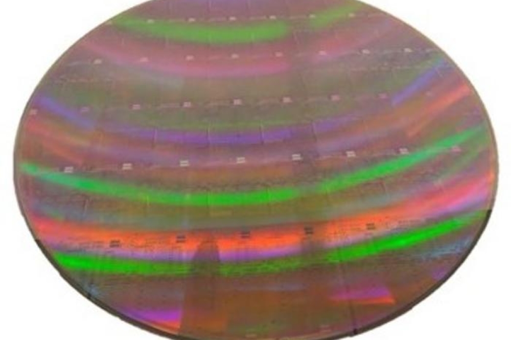
Figure 3. AlN growth rate as a function of trimethylaluminium (TMAl) molar flow rate (left) and a two-dimensional thickness map of an AlN film grown on a 50 mm sapphire substrate (right) using the AgniGaN 400 reactor. A 2 mm edge exclusion was applied in the thickness uniformity analysis.
We have also obtained electrical data for AlN films, with measurements from over 150 AlN samples, grown on native AlN substrates using RIS and CIS Agilis 100 reactors at Agnitron Technology and Arizona State University (ASU) (see Figure 2 (a) for a summary of the results). Included in these measurements is electrical data from samples produced on the recently commissioned Agilis 100 reactor installed at ASU, which is equipped with the RIS showerhead geometry. To ensure Hall measurements are reliable, a 70-80 nm highly conductive AlGaN contact layer (carrier concentration of more than 10¹⁹ cm-3, and a resistivity of 15 mΩ cm) is deposited on the AlN surface using the Agilis reactors. After depositing metal contacts at the four corners of the samples, etching AlGaN exposes the AlN surface, enabling stable Hall measurements with both DC and AC Hall systems.
Measurements reveal free-carrier concentrations in the AlN layers ranging from around 3 x 10¹⁴ cm-3 to 4 x 10¹⁶ cm-3 and electron mobilities between about 6 cm2 V-1 s-1 and 221 cm2 V-1 s-1 . A clear trend is observed, with a high mobility occurring at a low carrier concentration (me around 221 cm2 V-1 s-1, for n around 3 x 10¹⁴ cm-3), and higher carrier concentrations leading to lower mobilities (for example, µe around 15 cm2 V-1 s-1 , for n around 4×10¹⁶ cm-3). These electrical properties are realised through systematic variation of various growth parameters, including pressure, substrate temperature, silane flow rate, and V/III ratio. After process optimisation, comparable electrical results are obtained from growth on Crystal IS and Hexatech substrates, although somewhat different growth temperatures are required.
One important finding is the similarity in results across different platforms and users. For this study, most samples were grown by us in our RIS Agilis 100 reactor – but we also produced some using the CIS configuration, and they show similar performance. Data from the RIS Agilis 100 reactor installed at ASU closely matches our own results, highlighting the reproducibility of our Agilis platform across different installations. Nearly all samples grown in the Agilis reactors are conductive, with most exhibiting a bulk resistivity below 30 Ω cm. The lowest resistivity is around just 11 Ω cm (µe around 15 cm2 V-1 s-1, and n around 4 x 10¹⁶ cm-3), a substantial improvement over the best previously reported value of around 28 W cm [4].

Figure 4. X-ray rocking curves of a 6 µm-thick AlN film grown on a
sapphire substrate using the AgniGaN 400 reactor: (002) reflection
(left) with a FWHM of about 95 arcsec and (102) reflection (right) with a
FWHM of about 228 arcsec, indicating low screw and edge dislocation
densities in the film.
Recently, we integrated a high-power deuterium vacuum ultraviolet (D₂-VUV) source directly into the showerhead gas distribution flange of our RIS Agilis 100 reactor. The benefits of introducing a source of UV are a suppression of compensating defects and enhanced silicon dopant activation in AlN. Compared with previously employed mercury-xenon lamps, the deuterium source delivers a much stronger photon energy, above the AlN bandgap, making this form of illumination especially effective and efficient when supporting the growth of ultrawide-bandgap semiconductors.
According to secondary ions mass spectrometry, D₂-VUV exposure has a negligible impact on impurity levels, with oxygen background concentrations around 4 × 10¹⁶ cm-3 and carbon concentrations at the detection limit. Based on these findings, improved electrical performance is not associated with a reduction in impurity incorporation, and should be attributed to improved dopant activation and/or suppression of compensating defects.
We have also conducted Hall measurements on our AlN films grown under D₂-VUV exposure. These measurements determined a free-electron concentration of about 2.9 × 10¹⁶ cm-3 and electron mobility of about 80 cm2 V-1 s-1, corresponding to a resistivity of around 2.74 W cm. This value, amongst the lowest ever reported for silicon-doped AlN by MOCVD, highlights the important role D₂-VUV plays in improving the electrical performance of AlN.
AgniGaN 400 horizontal reactor
We have recently expanded our portfolio of MOCVD reactors with the AgniGaN 400, a system designed for the growth of GaN, AlN, and AlGaN thin-films at high growth rates. We developed this horizontal-flow reactor for the Naval Research Laboratory (NRL) under an SBIR Phase II programme funded by the Office of Naval Research (ONR). The AgniGaN 400 operates over a wide pressure range, from low pressures up to above atmospheric pressure growth. The system can accommodate three 2-inch wafers, or one 4-inch wafer, and reach substrate temperatures up to 1350 °C.
To evaluate the performance of this reactor, we have grown AlN and AlGaN layers on sapphire and native substrates. Trials have focused on key metrics, such as growth rate, thickness uniformity, crystal quality, and electrical properties.

Figure 5. Nd-Na profiles of MOSFETs measured from 22 spots on a 1-inch iron-doped (010) Ga2O3 wafer.
Our AgniGaN 400 is a multizone gas flow design, facilitating separate delivery of metalorganic precursors (alkyls), hydrides, and pushing gases into the reaction zone. By optimising the total gas flow rate through the injection system, one can control premature gas-phase reactions, growth rate, and thickness uniformity. One feature of the AgniGaN 400 is a heated gas injection port, capable of reaching +150 °C – this enables the use of low-vapour-pressure precursors, such as those required for materials like AlScN.
Users of the AgniGaN 400 can produce high-quality AlN and AlGaN films at high growth rates. Under optimised growth conditions, we realise AlN growth rates exceeding 6 mm/hr (see Figure 3, left), limited only by the maximum aluminium precursor flow. Thickness uniformity measurements of AlN films grown on sapphire show a 1σ non-uniformity of around 1.2 percent across a 50 mm wafer (see Figure 3, right).
Another strength of these AlN films is their low dislocation densities. Engineers at NRL have characterised the AlN layers we grew on sapphire with thicknesses ranging from around 2.6 µm to 6.0 µm. XRD rocking curves for an AlN film around 6 µm-thick have FWHM values of 95 arcsec for the (002) reflection and 228 arcsec for the (102) reflection. For thinner films, FWHM values are slightly higher, ranging from 107 arcsec to 95 arcsec for the (002) plane and 258 arcsec to 228 arcsec for the (102) plane, due to a reduction in screw and edge dislocation densities with increasing film thickness. These results reveal that the structural quality of AlN films grown using the AgniGaN 400 reactor is comparable to the best results reported in the literature.

Figure 6. Hall mobility map of MOSFETs measured from 22 spots on a 1-inch iron-doped (010) Ga2O3 wafer.
We have also evaluated our AgniGaN 400 for conductive AlGaN growth, for aluminium compositions from 65 percent to 90 percent. For aluminium contents below 80 percent, we have produced conductive AlGaN layers with carrier concentrations up to 1 x 1019 cm-3 and electron mobilities exceeding 50 cm2 V-1 s-1 , asserting our system’s capability to produce high-quality AlGaN. We have also produced an Al0.83Ga0.17N/Al0.66Ga0.34N HEMT structure featuring a two-dimensional electron gas mobility around 150 cm2 V-1 s-1 and a sheet charge density of about 5 x 1012 cm-2. These values validate our reactor’s suitability for growing device-quality AlGaN heterostructures.
Further evaluation of the electrical quality of AlN films produced with the AgniGaN 400 reactor has come from the characterisation of intentionally silicon-doped AlN layers, grown on native AlN substrates. Using the Hall method, we determined the electron mobility of these films, with thicknesses ranging from around 1.3 µm to 4.0 µm, and benchmarked the results against those obtained from AlN films grown with our Agilis 100 reactors (see Figure 2 (b)). Our measurements reveal that AlN layers grown in the AgniGaN 400 reactor exhibit free-carrier concentrations of around 3.1 x 10¹⁵ cm-3 to 1.6×10¹⁶ cm-3 and electron mobilities ranging from about 15 cm2 V-1 s-1 to 70 cm2 V-1 s-1, corresponding to bulk resistivities of around 17-50 Ω cm.
Based on these results, we conclude that the electrical performance of AlN films grown with the AgniGaN 400 is comparable to those obtained using our Agilis 100 platforms. This is very encouraging, given the limited experiments performed, and a growth process that’s still to be fully optimised. Even now this reactor is delivering high-quality AlN films with bulk resistivity as low as around 17 Ω cm – that’s a value comparable to results realised with our Agilis reactors, and significantly better than many values reported in the literature [4].
Nitrogen doping of Ga2O3
As well as advancing the growth of Al(Ga)N, we remain at the forefront of MOCVD reactor and process development of Ga2O3. Since 2018, we have introduced two Ga2O3 multi-wafer platforms; the Agilis 500, which supports up to one 4-inch wafer; and the Agilis 700, which accommodates up to one 6-inch wafer. Both these systems employ susceptor rotation speeds up to 2000 rpm, key to enabling excellent film uniformity and crystal quality. Using these platforms, we have demonstrated record Ga2O3 performance, including exceptional purity, record low-temperature electron mobility above 23,000 cm2 V-1 s-1 [5], and controllable doping from the low 1015 cm-3 to above 3 x 1020 cm-3.
One problem plaguing Ga2O3 lateral devices since the explosion of Ga2O3 research in the 2010s is the accumulation of silicon at the interface between the native substrate and the epitaxial layers. This accumulation creates a secondary conduction channel that increases reverse-bias leakage currents and introduces inconsistencies to MOSFET threshold voltages. Traditionally, HF etching prior to epitaxial growth suppresses the silicon peak, but this adds extra steps to pre-growth cleaning [6].
Recently, a number of research groups have investigated the use of nitrogen as a compensative dopant in gallium oxide, spurring interest in its use in lateral FETs. Over many years, we have carried out a comprehensive evaluation of nitrogen as a potential Ga2O3 dopant, using dilute ammonia, nitric oxide and nitrogen dioxide. All these nitrogen-incorporating sources have pros and cons. When nitrogen dioxide is employed as the main oxidizer, a high chamber pressure is needed to efficiently decompose this oxide into nitrogen and oxygen, leading to high particle concentration that degrades epitaxial quality. Switching to nitric oxide works well for incorporation to the mid-1018 cm-3, which may be sufficient for certain applications, but the silicon spike at the surface of the Ga2O3 substrate often rises to the low-1019 cm-3, and nitric oxide fails to fully compensate for this charge. The third candidate, ammonia, has a very linear incorporation rate from low 1016 cm-3 to high 1019 cm-3, giving it great flexibility in structure growth [7]. However, as ammonia incorporates hydrogen along with nitrogen, this threatens to counter the desired resistive effects. Note, though, that this has not been observed in any electrical results to date.
As part of our SBIR programme on large-area Ga2O3 FET development, we have used ammonia when producing a nitrogen-doped buffer layer, to separate the FET channel from the substrate interface. According to capacitance-voltage profiling, the nominal nitrogen concentration, 6 x 1018 cm-3, completely removed any observable interfacial charge (see Figure 5).
Our FET structure, grown on a 1-inch (010) iron-doped Ga2O3 substrate, consists of a low-temperature nucleation layer, a 100 nm-thick nitrogen-doped buffer, a 120 nm-thick unintentionally doped layer, and a 65 nm-thick silicon-doped channel. Capacitance-voltage measurements at 22 locations across the wafer have determined a uniform difference between the density of donors and acceptors of 1.6 x 1018 cm-3, and no detectable interface conductivity, indicating that nitrogen compensation effectively suppresses the interfacial silicon contribution. Mobility mapping (see Figure 6) has offered additional evidence of excellent uniformity, with an average mobility around 104 cm2 V-1 s-1 at n of about 8 x 1017 cm-3 and a 1σ non-uniformity of around 1.5 percent.
These advances in Ga2O3, as well as those on AlN and aluminium-rich AlGaN, highlight the critical role that we are playing in advancing the epitaxy of ultra-wide bandgap semiconductors.
This work was supported by the Defense Advanced Research Projects Agency (DARPA) under Contract No. 140D0424C0048 (Dr. David Meyer) and by the Office of Naval Research (ONR) through the SBIR Phase II programme under Contract No. N6833520C0105 (Mr. LJ Petersen). The work on the Ga2O3 supported by a Direct to phase II SBIR project funded through AFRL under contract No. FA239423CB010 (programme monitor Dr. Adam Neal). The views, opinions, and/or findings expressed are those of the author and should not be interpreted as representing the official views or policies of the Department of War or the U.S. Government. Agnitron also acknowledges Prof. Houqing Fu of Arizona State University for collaboration on the electrical characterisation of AlGaN and AlN layers, Prof. Travis Anderson of the University of Florida for Hall measurements that confirmed the electrical data, and Dr. Emma Rocco and Dr. Frank Kelly of the Naval Research Laboratory for XRD measurements of AlN samples.