A new foundation for the InP HBT
Combining InP HBTs with Soitec’s SmartCut technology creates a cost-effective, sustainable InP-on-silicon technology for advanced communication systems.
BY ABHITOSH VAIS FROM IMEC
Throughout this century, communication systems have been driving the useable frequency spectrum to higher values. It’s a direction of travel that facilitates higher bandwidths; and ultimately high data rates, low latency and gains in energy efficiency.
This trend shows no sign of abating, with demand strong for more and faster data connectivity. But the semiconductor technology that forms the backbone of these communication systems is now at an inflection point. The troublesome concern is that the technologies currently available for critical system components, such as power amplifier (PA) modules, are no longer meeting the performance and energy efficiency required by communication systems while operating at such high frequencies (see Figure 1). Motivated by this limitation, new materials and devices are being explored to fulfil these requirements.

Figure 1. Technological trends in output power, Psat, followed by different technologies with respect to operating frequencies. Solid lines are only to guide the eyes. [H. Wang et al., “Power Amplifiers Performance Survey 2000-Present,” [Online]. Available: https://gems.ece.gatech.edu/PA_survey.html
Speeding communication with III-Vs-on-silicon
Within the family of compound semiconductors, III-V-based devices, and HBTs in particular, are strong contenders for next-generation high-speed communication systems. The latter class of device has generated significant sales for decades, with GaAs/InGaP HBTs grown on small size native GaAs substrates widely deployed in mobile phones, thanks to several advantages over other material combinations.
However, the technologies for high-speed communication systems, such as 6G and advanced wireline applications, require better RF performance. In particular, they need to excel when judged against a number of key metrics – they are the cut-off frequencies ft and fmax, the output power (Pout), and the power-added efficiency (PAE) – while offering the opportunity for high-volume production at a significantly lower cost, as well as providing flexibility in circuit design, and having a smaller chip footprint.
It’s possible to fulfil all these requirements with the integration of III-Vs on silicon substrates, using a state-of-the-art CMOS back-end-of-the-line (BEOL) process for routing complex control signals (see Figure 2).
When considering whether to pursue this approach, one should note that there’s a significant challenge when integrating III-Vs, such as GaAs or InP, with silicon: a large lattice mismatch. Due to this issue, epitaxial growth spawns defects, with subsequent integration leading to a defective material system and unsatisfactory performance.

Figure 2. III-V and silicon CMOS have their own advantages. When
combined together in a hybrid technology, they can provide a solution
for future RF applications.
One option for circumventing this issue is a form of heterogenous integration that separates the III-V front-end-of-line (FEOL) and CMOS BEOL fabrication processes, and uses flip-chip bonding to subsequently unite the modules. It is a modus operandi that provides high-quality III-V devices on silicon, but at the expense of significant wastage of precious III-V material. Given the geo-political significance and scarcity of such material, the cost and sustainability of a technology will probably define its useability.
A hybrid III-V/CMOS technology
Given this concern, an attractive alternative is to transfer a thin III-V film from a native III-V substrate, instead of bonding a whole substrate to the target silicon wafer. With this approach, the thin III-V film provides a foundation for the growth of a good quality III-V device stack.
Helping those that wish to explore this approach is Soitec’s recently developed process for transfering thin films of InP from native substrates to silicon target wafers. It’s a technology that’s scalable to 200 mm and 300 mm silicon wafers, and allows the native pseudo-donor wafer to be re-used for several cycles of transfer. Strengths of this technology include maintaining the quality of InP when it’s on silicon, and consuming very little of the latter, thereby ensuring it’s an environmentally sustainable solution.
At imec, our team is adopting this approach. In our case, we are working on the development of a hybrid III/V-CMOS technology that utilises
InP-on-silicon wafers, employing them as a foundation for fabricating InP HBTs on 200 mm silicon wafers. Success on this front would deliver scaled process control and high-volume integration capabilities with CMOS. These attributes could be a game-changer for the InP HBT, which is currently limited by lab-like production environments. Our advance promises to provide a cost-effective solution for meeting high-performance and scalability demands of future communication applications.

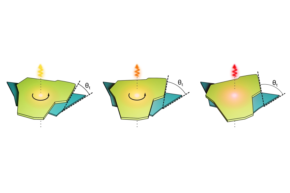
Figure 3: A cartoon illustration of the Smart-Cut process of
transferring thin films of InP onto a silicon substrate. [B. Ghyselen, et al., Digests of 2023 International Conference on Compound Semiconductor Manufacturing Technology (2023)].
Growing InP HBT stacks
The starting point for our efforts is Soitec’s 100 mm InP-on-silicon substrates, which features a thin film of InP (approximately 0.5 µm) that’s transferred to a 100 mm silicon wafer. We load these engineered substrates into an MOCVD chamber and grow an InP HBT stack.
To check the quality of the epilayers, we use two common characterisation techniques: atomic force microscopy (AFM), for surface quality; and high-angle annular dark-field scanning transmission electron microscopy (HAADF-STEM), for epitaxy quality. With AFM, we find the root-mean-square roughness, a measure of surface quality, is similar for our InP-on-silicon structures and those grown on InP. On both platforms, root-mean-square roughness is around 0.13 nm, a value that indicates good epitaxial growth (see Figure 4 (a) for AFM scans)).
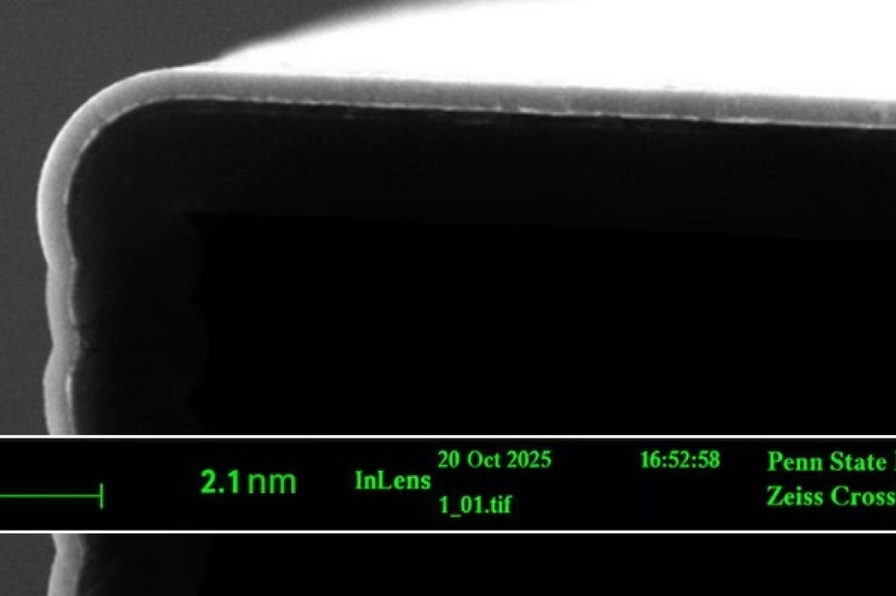
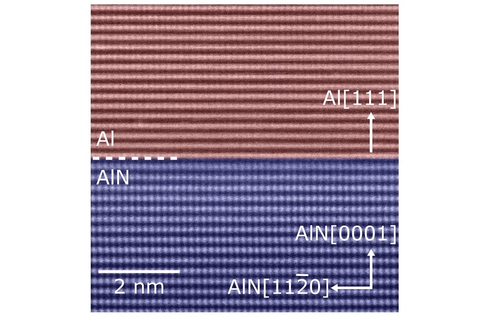
Additional evidence of epitaxial growth quality is found in HAADF-STEM images (see Figure 4 (b)). Interfaces are sharp and free from defects.
We use verified, high-quality HBT stacks to fabricate our devices. These transistors are evaluated, to assess both their electrical performance and that of the epi-stack.
Our investigations have considered transfer characteristics, using the Gummel plot. Analysing this data has allowed us to extract a number of metrics, including DC current gain (b), the ideality factor of the current-voltage characteristics (nbase/ccollector), and the leakage current of the heterojunctions. Ideality factor and leakage current are good metrics for epitaxial and heterojunction evaluation, and DC current gain is a good indicator of device performance.

Figure 4. A 2 µm x 2 µm atomic force microscopy scan (a) (and
corresponding root-mean-square (rms) values (b)) of the top device
surface on InP and InP-on-silicon substrates. (c) A high-angle
annular dark-field scanning (HAADF-S) transmission electron microscopy
(TEM) image of InP HBT stack grown on InP-on-silicon with insets
representing: (top), InP/GaAsSb/InP interface; (bottom), InP/InGaAs/InP
interface.
Benchmarking performance
When we compare the ideality factor of the base current of our device fabricated on the Soitec platform and our control, we find no clear difference. This highlights the good quality of our InP-on-silicon HBTs.
We obtained similar results when studying leakage currents, but uncovered a difference in peak DC current gain, b, at a base-emitter voltage of 1 V: a value of 30 for the HBT on the native substrate, and around 56 for that on InP-on-silicon. We attribute this variation to a difference in the effective doping of the base layer, a view supported by transmission-line measurements that determine the sheet resistance and contact resistivity of the base layer on both substrates. Differences in doping stem from variations in the effective growth temperature on the surface of InP and InP-on-silicon substrates, a consequence of the presence of a thick buried-oxide layer in the heterogeneous device. It’s possible to match the gain in both forms of HBT by carefully calibrating the base doping level for epilayers grown on the InP-on-silicon substrates.
Another metric for evaluating device performance is breakdown voltage. A higher value is a valued asset, as it tends to define the operating limits of the system – and higher breakdown voltages hold the key to higher-power generation. We have not observed any discernible difference in the breakdown voltages of our HBTs on InP and InP-on-silicon substrates. This finding provides further corroboration of the quality of the epitaxial growth on the InP-on-silicon substrate.
It’s not enough to evaluate a technology for RF applications with only DC metrics. RF evaluation is essential, but demands special metrology structures. In addition, it critical to undertake careful calibration of the measurement setup, using dedicated calibration structures and strategies for correct data analysis.
To fulfil these criteria, we fabricated RF devices and structures on InP and InP-on-silicon substrates, for RF characterisation of our HBTs. This allows us to determine the impact of InP-on-silicon wafers on RF performance.
A key finding from this work is that HBTs on both substrates have a cut-off frequency of up to around 140 GHz. While this performance is not on a par with the state-of-the-art, it confirms that InP-on-silicon substrates provide a good alternative for the fabrication of InP HBTs, as there’s no degradation in performance.
Self-heating and thermal management
HBTs have great potential to generate highly-efficient, linear power at RF and millimetre-wave frequencies. But these high output-power densities come with a catch – significant heat generation in the active device region. As temperatures rise, driven by heat generation, device performance may decline, and in the worst case, the chip can even burn. So, it’s imperative to have a path for efficient heat removal from the device, and even the chip as a whole.
While GaAs- and InP-based HBTs have a superior high-speed performance with a higher drive voltage than their silicon CMOS and bipolar counterparts, they are more prone to self-heating effects. This issue stems from the relatively poor thermal conductivity of the III-V materials, including the internal III-V ternary compounds. For example, InGaP, InGaAs and GaAsSb all possess thermal conductivities that are an order of magnitude lower than those for silicon. These factors are responsible for aggravated thermal issues that threaten to degrade device performance and impact device reliability. Due to this, thermal management is key to realising high-performance InP HBT heterogeneous integration.
In addition to these issues associated with III-V materials, InP-on-silicon substrates contain a layer of SiO2, another poor thermal conductor. There’s the fear that this could exacerbate the thermal management of HBTs on InP-on-silicon substrates.
To investigate the impact of the oxide layer on the thermal performance of InP-on-silicon substrates, we have performed extensive thermal simulations, using an in-house 3D thermal simulator. This work indicates that the thickness of this oxide layer plays an important role in defining the efficiency of heat removal on InP-on-silicon substrates. We have also noticed that trimming the oxide thickness to below 50-100 nm diminishes its impact significantly, so that this structure is equivalent to that without an oxide layer.
These insights, provided by our simulations, are an important step towards achieving a thermally efficient InP-on-silicon solution for high-speed communication systems based on InP HBTs. Encouraged by these findings, we are devoting significant effort to practical implementation on InP-on-silicon substrates. The outlook appears to be positive.
We have no doubt that cost-efficient, sustainable integration of III-Vs on silicon is critical for the success of future high-speed communication systems. The current state-of-the-art on InP and/or transferred substrates might fail to satisfy some of these requirements in high-volume production applications – but InP-on-silicon substrates promise to provide a sustainable solution.
Our efforts have demonstrated that devices fabricated on InP-on-silicon can deliver a similar performance to those formed on InP; and that InP HBT technology that incorporates an InP-on-silicon foundation could be a cost-effective solution for meeting the high-performance and scalability demands of future applications.