Scaling the growth of novel materials

From 4-inch gallium oxide films to next-generation
transition metal dichalcogenides, Agnitron’s US-driven breakthroughs on
large-area wafers are ushering in a new era of semiconductor devices.
BY WILLIAM BRAND, AARON FINE, FIKADU ALEMA, PAUL FABIANO AND ANDREI OSINSKY FROM AGNITRON
In the fledgling days of our industry, production of compound semiconductor devices just involved those based on GaAs and InP. But over a number of decades, our palate has expanded to include a number of new materials with more impressive characteristics. Devices made from GaN are now serving in the optoelectronic, RF and power domains, where they are generating substantial revenues, and SiC is supporting a revolution in mobility. But that’s by no means the end of our journey. Now piquing much interest is gallium oxide (Ga₂O₃), an ultra-wide bandgap material that promises to deliver unprecedented efficiencies in electrical systems, and transition metal dichalcogenides (TMDs), which could spur advances in electronics, energy storage and sensors.
Helping to usher in a new era for compound semiconductor devices that is driven by the introduction and uptake of Ga₂O₃ and TMDs is our company, Agnitron Technology. For nearly a decade, we have been leading the development of advanced MOCVD reactors and processes for high-quality Ga₂O₃ and its alloys, and more recently we have been expanding our reach into TMDs. Due to this, our MOCVD systems are now deployed at leading universities and research institutions worldwide, supporting cutting-edge Ga₂O₃ and TMD research.
More recently, we focused on scaling our MOCVD technology to support multi-wafer and large-area Ga₂O₃ growth. In 2018, we introduced two new multi-wafer MOCVD platforms, both designed explicitly for Ga₂O₃. These reactors feature susceptor rotation speeds up of to 2000 revolutions-per minute (RPM), key to enabling excellent film uniformity and crystal quality. Our Agilis 700 supports wafer loading of up to one 6-inch wafer.
Working with our partners, we have used these platforms to demonstrate record-breaking material performance. Highlights with the Agilis 500 include the growth of Ga₂O₃ thin films with exceptional purity and a record low-temperature electron mobility, exceeding 23,000 cm²/ V-1 s-1 [1]. Additional triumphs with our Agilis platform are: controllable doping down to low 1015 cm-3, a pre-requisite for drift layers in vertical power devices; and through the optimisation of silicon doping, conductivity values surpassing 2500 S cm-1, corresponding to free-carrier concentrations of 3.4 × 10²⁰ cm-3 [2]. Similar high-doping results have been independently reported by researchers from the Naval Research Laboratory (NRL) on an Agilis 500 tool operating at high rotation speeds [3].

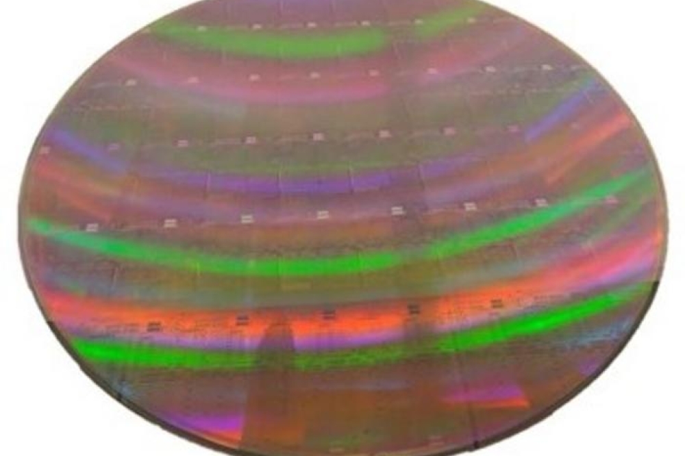
Figure 1. Two-dimensional thickness map of Ga₂O₃ film grown on a 4-inch sapphire substrate using the Bowtie showerhead. The growth rate was 2 μm/hr, and a 2 mm edge exclusion has been applied during thickness mapping.
Innovation in Gas injection: The Agilis 700 platform
We are continuing to pioneer advancements in semiconductor manufacturing equipment, exemplified by our newly redesigned Agilis 700 MOCVD platform. Central to this innovation is a novel gas injection methodology, replacing traditional central-injection and checkerboard patterns with an all new advanced Close-Injection Showerhead approach. By ensuring precisely controlled precursor flows in separated zones directly above the substrate surface, this refinement minimises gas-phase reactions and precursor depletion. The improved control delivers significant gains in uniformity and material quality – critical for large-area wafer deposition, and evidenced by recent preliminary electrical results from pioneering 4-inch Ga₂O₃ devices.
The Agilis 700 underscores our commitment to scalability and flexibility, providing a robust platform for both research and production. It supports various substrate configurations, and can accommodate seven 2-inch wafers, a single 4-inch wafer or even a 6-inch wafer, all without compromising growth uniformity or material quality. Sharing core design features with its predecessors – the Agilis 100 (up to 3-inch wafers) and Agilis 500 (up to five 2-inch wafers) – the Agilis 700 bridges the gap between R&D and production, enabling seamless process translation across scales.
As well as providing a range of tools for research, we serve the needs of high-volume manufacturers through our GOX300 platform, an automated, production-focused MOCVD system. This mass-production tool builds on the reactor technology and scalability principles of our Agilis line while incorporating automation and advanced process control that’s tailored to industrial semiconductor production. The GOX300 allows manufacturers to access high-throughput, high-uniformity processing, which is essential for commercialising next-generation electronic and optoelectronic devices.
We are very active in equipment innovation, with efforts extending further into reactor design, the optimisation of deposition efficiency, and supporting high-performance materials growth across a wide range of semiconductor applications.

Figure 2. Effect of susceptor rotation speed on film uniformity and growth rate
Revolutionising deposition: The RDR reactor
Our proprietary Rotating Disc Reactor (RDR) is the core of our oxide MOCVD systems, including the Agilis 700. With over 16 years of innovation, our engineering legacy can be traced back to early RDR simulations at Sandia and MIT Lincoln Lab. While others with an interest in epitaxy focused on theory, we grasped the RDR’s commercial potential – especially for wide and ultra-wide bandgap semiconductors.
This led to a dedicated effort to optimise our RDR for materials like Ga₂O₃ and AlN. Significant successes have followed, including the deposition of the highest-purity Ga₂O₃ film reported to date, solidifying our leadership in oxide MOCVD. Since 2018, our team and equipment users have contributed to over 250 peer-reviewed publications and conference papers focused on the epitaxial growth and device applications of Ga₂O₃.
Key to our success is our patented showerhead design that enables precise flow and thermal stability while preventing unwanted wall deposition – a common shortcoming in traditional systems.
The RDR’s dimensionless process equations also allow it to scale easily, from a single 2-inch wafer to 21 x 2-inch configurations and even 12-inch substrates.
As we continue to advance our platform, our domestic innovation and our collaborative partnerships remain central to our mission.

Figure 3. Two-dimensional atomic force microscopy (AFM) images taken from five locations on a roughly 300 nm-thick Ga₂O₃ film grown on 2-inch Synoptic substrates using Bowtie Showerhead on the Agilis 700 reactor. The scan area is 5 × 5 μm²
Scaling Ga₂O₃ to 4-inch wafers
Equipping our Agilis 700 reactor with an all-new gas-distribution flange that’s optimised for growth of β-Ga2O3 on large-area substrates ensures the growth of highly uniform epitaxial films. Vital to this optimisation is the support that’s come from the Air Force Research Laboratory (AFRL) through the SBIR direct to Phase II program.
For this work, we selected trimethylgallium (TMGa) as the gallium precursor, due to its ability to facilitate faster deposition rates than the more conventional triethylgallium (TEGa), commonly used for Ga₂O₃ growth. Our films were grown under the following conditions: 800 °C growth temperature, 25 Torr chamber pressure, 800 RPM susceptor rotation, and a molar flow for TMGa of approximately 240 µmol min-1.
A key concern when using TMGa is the potential for carbon incorporation, introduced during decomposition of the methyl groups. Note that with TEGa, the threat of carbon contamination is avoided, due to different breakdown mechanisms. When we use TMGa, we mitigate the risk of carbon incorporation by maintaining a VI/III ratio above 500 – this condition has been previously identified as the threshold for avoiding carbon incorporation and ensuring film purity. Under these optimised conditions, we reached growth rates of around 2 µm hr-1, resulting in films with a thickness of around 1 µm. According to 121-point reflectivity mapping on a 4 inch substrate, thickness non-uniformity is just 1.39 percent. Realising this level of uniformity is essential for the scalability and reliability of Ga₂O₃-based devices.
As part of our study into Ga2O3 thin-film growth on 4-inch substrates, we examined the effect of susceptor rotation speed on growth rate, varying RPMs up to 1200. We identified a clear linear trend between 400 RPM and 1200 RPM, where the growth rate increased from 1.8 µm hr-1 to 2.0 µm hr-1. This increase is accompanied by little change in thickness non-uniformity, which remained stable across the RPM range. All our samples within this range exhibited a 1s value of less than 2 percent (the best value, just mentioned, is 1.39 percent, at 800 RPM). However, we found that reducing the RPM below 400 led to a more rapid decrease in growth rate, and a significant increase in non-uniformity. For instance, at 200 RPM, non-uniformity jumps to approximately 3.5 percent, and at 0 RPM, it increases to 9 percent.

Figure 4. Hall mobility (left) and free electron concentration (right) maps for a 65 nm-thick FET channel grown on a roughly 200 nm-thick unintentionally doped Ga₂O₃ layer on 2-inch Synoptic (010) β-Ga₂O₃ substrates.
These results highlight that with our new gas-injection scheme, it is critical to maintain a high-speed rotation to ensure optimal growth rates and uniformity. The increased non-uniformity at lower RPMs also suggests that slower rotation speeds hinder diffusion of precursors, hampering controlled growth.
Due to the limited availability of native 4-inch Ga₂O₃ substrates, we have also investigated the surface morphology and the electrical properties of Ga₂O₃ films grown on native 2-inch (010) substrates. For this study, we formed an epitaxial structure consisting of a low-temperature nucleation layer, followed by 200 nm of unintentionally doped material, and a 65 nm silicon-doped layer. This stack is designed for the fabrication of a lateral FET, a common Ga₂O₃ device.
Through optimisation of parameters – 800 °C growth temperature, 25 Torr chamber pressure, and 48 µmol min-1 TEGa molar flow – we achieved a film thickness non-uniformity of just 0.83 percent. According to Atomic Force Microscopy (AFM), there is a uniformly smooth surface across the 2-inch wafer. Across five mapped locations, 5 µm x 5 µm AFM images show an average root-mean-square roughness of 1.02 nm. We attribute this high level of uniformity to the enhanced gas-injection system, which uses separate injection zones for metalorganic precursors and oxygen. This configuration improves adatom diffusion prior to oxidation, reducing surface roughness and improving film quality.
To assess the electrical properties of our films, one of our partners, Soctera Inc, fabricated Hall-effect pads and capacitors across the wafer. Measuring a total of 22 devices on our 2-inch sample determined an average electron mobility of 138.4 cm² V-1 s-1 and a mobility non-uniformity of 3.8 percent. The highest value recorded for electron mobility was 147 cm² V-1 s-1. Average bulk electron concentration for the devices was 4 x 10¹⁷ cm-3. Capacitance-voltage measurements of the channel region indicate a higher electron concentration of 7.3 x 10¹⁷ cm-3, with an electron concentration non-uniformity of 8 percent. Using this reactor, a roughly 2 µm-thick unintentionally doped (UID) Ga₂O₃ film exhibited high electron mobility (around 179 cm² V-1 s-1 and low carrier concentration (9.9×10¹⁵cm-3). Further reduction of residual carrier concentration is possible through adjusting the oxygen-to-gallium ratio in the gas phase. These results demonstrate the reactor’s capability to grow device-quality epitaxial films with excellent thickness and doping uniformity across a 2-inch wafer.
Through recent experiments, we have developed a process achieving 2.5 x 1020 cm-3 electron concentration and 42 cm² V-1 s-1 electron mobility with RMS roughness values of less than 0.5 nm. In the future, we plan to use this process as an ohmic regrowth for the source and drain terminals in the FETs to greatly improve our contact resistance.
Based on all these measurements of electrical characteristics, we conclude that our films are of excellent quality, with mobility values and electron concentrations that are promising for the future scalability of this growth technology. When larger native substrates become more readily available, this will unleash the promise of this growth method for large-scale device fabrication.
As highlighted in the preceding sections, the Agilis 700 equipped with the new gas-distribution flange has shown outstanding results in film material quality and uniformity. To access another aspect of film growth, we began experimenting with the growth of gallium oxide alloys, specifically aluminum gallium oxide.
Using our standard growth conditions, as preciously described, we grew around 70-80 nm of (AlxGa1-x)2O3 with 100 nm of UID Ga2O3 on 2-inch c-plane Sapphire and (010) β-Ga2O3 substrate from Synoptics. For our metal-organic aluminum source, triethylaluminum (TEAl) was utilised for these experiments.
The films exhibited an excellent thickness non-uniformity of 1.2 percent over a 2-inch wafer. Surface roughness remained low with an RMS roughness value of 0.8 nm over a 5 µm x 5 µm scan area assessed by AFM. The composition of the
(AlxGa1-x)2O3 was determined to be around 20 percent aluminium using X-ray diffraction and can be seen in Figure 5. The observation of Pendellösung fringes indicate a highly abrupt transition from β-Ga2O3 to β-(AlxGa1-x)2O3 and low surface roughness of both β-Ga2O3 and β-(AlxGa1-x)2O3 layers. The success of uniform (AlxGa1-x)2O3 growth expands the capabilities of (AlxGa1-x)2O3/Ga2O3 heterostructures, enabling the development of epitaxial gate dielectrics and device structures such as HEMTs and MODFETs.

Figure 5. X-ray diffraction ω-2θ scan profile for β-(Al0.20 Ga0.80)2O3 /Ga2O3 grown on (010) β-Ga2O3 Synoptics substrate using Agilis 700 with the improved gas-distribution flange. The thickness of the β-Al0.20 Ga0.80 layer is 70-80 nm.
Advances in TMD growth
Building on our success in scaling ultra-wide bandgap materials, we have made significant progress in expanding scalable growth of two-dimensional (2D) materials, specifically TMDs, through MOCVD. These 2D materials, and particularly TMDs, are poised to revolutionise the electronics, optoelectronics, and quantum technologies.
The general formula for TMDs is MX₂: M is a transition metal, such as molybdenum or tungsten; and X is a chalcogen, like sulfur, selenium, or tellurium. Unlike graphene, which lacks a bandgap, many TMDs possess sizeable and tuneable bandgaps, often transitioning from an indirect bandgap in the bulk to a direct one in monolayer form, making them ideal for semiconductor applications. Another strength of these materials is their layered structure, which enables mechanical exfoliation or chemical synthesis into monolayers, characteristics well-suited to nanoscale devices and heterostructures.
Thanks to advances in large-area synthesis techniques for MOCVD, it’s now possible to deposit wafer-scale TMD films with sizes of 4 inches and beyond, while ensuring precise control over composition and thickness – this is critical for scalable electronic and optoelectronic device integration. However, there’s still work to do with MOCVD. Here, the key challenge is the temperature-dependent interplay between transition metal adatoms’ low surface mobility and the chalcogen species’ high desorption rate during film growth.
While high growth temperatures are needed to enhance the surface mobility of the metal and improve crystallinity over large areas, they also promote chalcogen desorption (loss), leading to vacancies and defects that compromise material quality.
Chalcogen vacancies also play a key role in determining the phase stability of TMD polymorphs. For instance, in MoTe₂, the concentration of tellurium vacancies dictates whether the semiconducting 2H phase forms, or the metallic 1T′ phase. These two phases are markedly different. The 2H phase features a hexagonal structure and exhibits a bandgap transition from indirect (around 0.8 eV in bulk) to direct (around 1.1 eV at the monolayer level), making it suitable for optoelectronic applications. Meanwhile, the 1T′ phase has an orthorhombic structure and metallic conductivity, offering potential for quantum and topological devices. Due to these substantial differences, precise process control during MOCVD is essential for tailoring MoTe₂ and other TMD materials to specific applications.

Figure 6. Images of the MOCVD-grown MoTe 2 on 4-inch h-BN/sapphire wafers at 600 °C and at 700 °C (inset).
Investing in the growth of TMDs by MOCVD makes much sense, because this technology is well suited to the growth of uniform films on large-area wafers. MOCVD offers tight control over critical parameters such as growth temperature and the chalcogen-to-transition metal flux ratio, which directly affect chalcogen vacancy concentrations and phase formation.
Over the past few years, we have been collaborating closely with Zakaria Y. Al Balushi’s team at the University of California, Berkeley, to advance MOCVD growth of TMDs. As part of this effort, we have refurbished and upgraded a high-speed rotating disc MOCVD reactor and supported process development to enable wafer-scale growth.
This partnership has provided new insight into how MOCVD growth conditions influence the uniformity and polymorph phase control of MoTe₂ on large-area wafers [4]. MoTe₂ films have been deposited using di-isopropyl telluride and molybdenum hexacarbonyl precursors, with hydrogen as the carrier gas. Growth has been conducted on 4-inch c-plane sapphire substrates, both bare and coated with ultra-flat hexagonal boron nitride (h-BN) layers, which were developed under the support of the AFRL through the SBIR direct to Phase II program. Nucleation on bare sapphire has proved challenging, while h-BN/sapphire templates – grown by our team and provided to our partners at Berkeley – have enabled more uniform growth.
Note that we have extensive expertise in MOCVD growth of high-quality 2D h-BN on substrates up to 6 inches in diameter. These h-BN layers have a number of applications, which include serving as ideal templates for GaN or AlGaN/GaN HEMTs, and acting as sacrificial layers for transferring devices onto high-thermal-conductivity substrates, such as diamond [5].
Our collaboration with the team at Berkeley has systematically investigated the effect of growth temperature on the optical properties of MoTe₂ thin films, using controlled MOCVD experiments that involve the growth of MoTe₂ on 4-inch h-BN/sapphire templates for 30 minutes. We have observed a distinct colour change with growth temperature, shifting from a darker brown at 600 °C (see Figure 6) to a pink hue at 700 °C (see Figure 6, inset), indicating changes in optical properties.
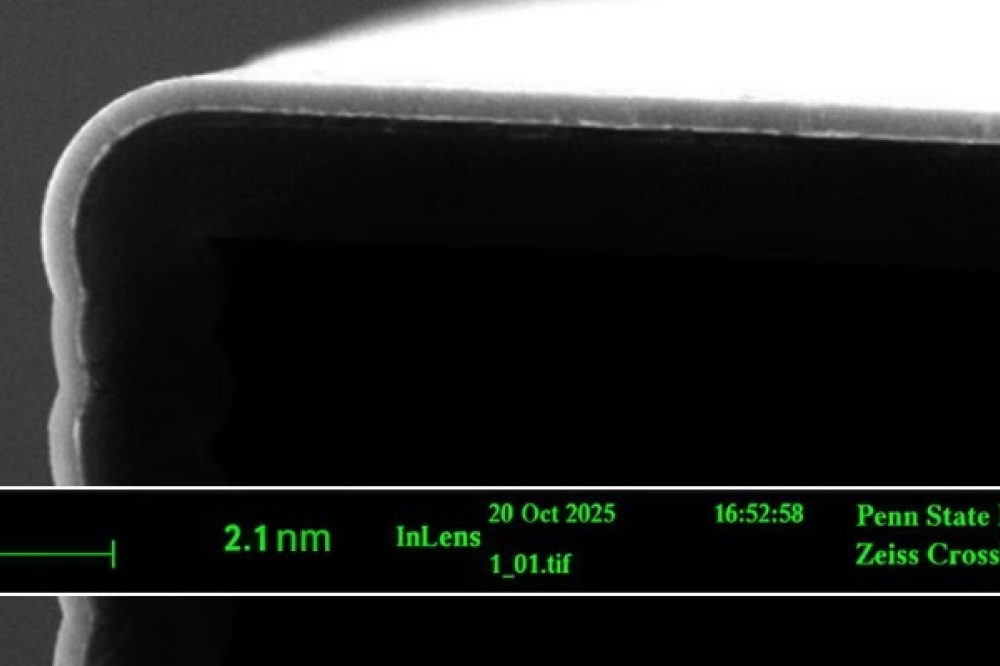
Greater insight into these films has been provided by cross-sectional scanning tunnelling electron microscopy. This technique reveals that MoTe₂ films grown at 600 °C exhibit well-crystallised bi- to tri-layers with a uniform molybdenum and tellurium distribution (see Figure 7 (a) and (b)). In contrast, growth at 700 °C produces non-uniform 1T′-phase layers with poor contrast in transmission electron microscopy images and signs of oxidation (see Figure 7 (c) and 7 (d)), despite consistent elemental distribution. The most probable cause of this degradation is the greater chemical reactivity and instability of the 1T′ phase.
These findings emphasise the critical role of temperature-induced tellurium vacancies in determining phase stability. In addition, they underscore the need for precise thermal control during MOCVD to tailor MoTe₂ for specific device applications. (For a more detailed analysis of these results, see the paper by B. J. Kim et al. ACS Nanoscience Au 5 1 (2025)).
Building upon these foundational research achievements, we have invested in significant equipment innovations to enable large-area wafer processing.

Figure 7. (a) Cross-sectional transmission electron microscopy image of 2H-phase MoTe₂ grown at 600 °C, showing a well-defined layered structure, and (b) the corresponding energy-dispersive X-ray spectroscopy maps confirming uniform elemental distribution of molybdenum and tellurium. (c) Cross-sectional transmission electron microscopy image of 1T’-phase MoTe₂ grown at 700 °C, revealing nonuniform layer formation and (d) energy-dispersive X-ray spectroscopy maps for the 1T’-phase sample, showing consistent distribution of molybdenum and tellurium despite structural irregularities.
Driving innovation through collaboration
Unlike our European counterparts, our growth is rooted in US-based partnerships and funding – particularly through the Air Force Research Laboratory (AFRL) and the Office of Naval Research (ONR) through the SBIR programs. These collaborations strengthen America’s domestic semiconductor infrastructure, and position Agnitron as a key contributor to national R&D and manufacturing efforts.
Looking ahead, we will continue delivering advanced MOCVD systems like the Agilis 700 to leading semiconductor hubs across the US and worldwide.
Built on innovation and technical excellence, we offer flexible tools for processing ultra-wide-bandgap semiconductors, III-nitrides, SiC, 2D materials, and oxides. Our systems are trusted by research institutions, government labs, and industry leaders alike.
From pioneering gas injection methodologies and RDR design to enabling the first release of electrical results from a 2-inch Ga2O3 device growth using a large scale reactor, we remain committed to enabling next-generation semiconductor breakthroughs – through responsive engineering, specialty materials expertise, and US-based manufacturing.
Acknowledgement: The work discussed here was primarily funded by the Air Force Research Laboratory (AFRL) through the Direct to Phase IISBIR program (Contract No.FA239423CB010), under the direction of Dr. Adam T. Neal. Agnitron also acknowledges support from the Office of Naval Research (ONR) through the STTR Phase II program (Contract No. N6833518C0192), under the direction of Mr. LJ Petersen. Agnitron would also like to acknowledge Prof. Travis Anderson of the University of Florida for conducting Hall measurements on our samples